

Online proceedings - EDA Publishing Association
Online proceedings - EDA Publishing Association
Online proceedings - EDA Publishing Association
- No tags were found...

You also want an ePaper? Increase the reach of your titles
YUMPU automatically turns print PDFs into web optimized ePapers that Google loves.
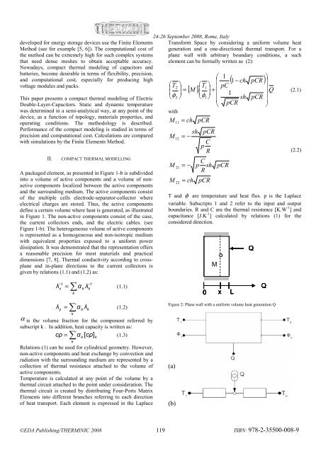
24-26 September 2008, Rome, Italydeveloped for energy storage devices use the Finite Elements Transform Space by considering a uniform volume heatMethod (see for example [5, 6]). The computational cost of generation and a one-directional thermal transport. For athe method can be extremely high for such complex systems plane wall with arbitrary boundary conditions, a suchthat need dense meshes to obtain acceptable accuracy. element can be formally written as (2):Nowadays, compact thermal modeling of capacitors andbatteries, become desirable in terms of flexibility, precision,and computational cost, especially for producing high⎛ 1⎞⎜ ( 1−ch pCR ) ⎟voltage modules and packs.⎛T⎞ ⎛2T ⎞1 ⎜ pC⎜ ⎟ ⎜ ⎟⎟(2.1)This paper presents a compact thermal modeling of ElectricDouble-Layer-Capacitors. Static and dynamic temperaturewas determined in a semi-analytical way, at any point of thedevice, as a function of topology, materials properties, andoperating conditions. The methodology is described.Performance of the compact modeling is studied in terms ofprecision and computational cost. Calculations are comparedwith simulations by the Finite Elements Method.II.COMPACT THERMAL MODELLINGA packaged element, as presented in Figure 1-b is subdividedinto a volume of active components and a volume of nonactivecomponents localized between the active componentsand the surrounding medium. The active components consistof the multiple cells electrode-separator-collector whereelectrical charges are stored. Thus, the active componentsdefine a certain volume where heat is generated, as illustratedin Figure 1. The non-active components consist of the case,the current collectors ends, and the electric cables. (seeFigure 1-b). The heterogeneous volume of active componentsis represented as a homogeneous and non-isotropic mediumwith equivalent properties exposed to a uniform powerdissipation. It was demonstrated that the representation offersa reasonable precision for most materials and practicaldimensions [7, 8]. Thermal conductivity according to crossplaneand in-plane directions to the current collectors isgiven by relations (1.1) and (1.2) as:⎜ ⎟=⎝φ2⎠withMMMM11122122[ M ].= chsh= −= −= ch⎜ ⎟+⎜⎝φ1⎠⎜⎝pCRpCRCpRCp shRpCRpCR1shpCR. Q⎟pCR⎟⎠(2.2)T and φ are temperature and heat flux. p is the Laplacevariable. Subscripts 1 and 2 refer to the input and outputboundaries. R and C are the thermal resistance [K.W -1 ] andcapacitance [J.K -1 ] calculated by relations (1) for theconsidered direction.MQ− 1λ = ∑αλ−xyk= ∑kkk1kk(1.1)λ α λ(1.2)α is the volume fraction for the component referred bysubscript k . In addition, heat capacity is written as:c ρ α [ cρ](1.3)= ∑kkRelations (1) can be used for cylindrical geometry. However,non-active components and heat exchange by convection andradiation with the surrounding medium are represented by acollection of thermal resistance attached to the volume ofactive components.Temperature is calculated at any point of the volume by athermal circuit attached to the point under consideration. Thethermal circuit is created by distributing Four-Ports MatrixElements into different branches referring to each directionof heat transport. Each element is expressed in the LaplacekQ0 xLFigure 2: Plane wall with a uniform volume heat generation Q(a)(b)©<strong>EDA</strong> <strong>Publishing</strong>/THERMINIC 2008 119ISBN: 978-2-35500-008-9


