

Online proceedings - EDA Publishing Association
Online proceedings - EDA Publishing Association
Online proceedings - EDA Publishing Association
- No tags were found...

Create successful ePaper yourself
Turn your PDF publications into a flip-book with our unique Google optimized e-Paper software.
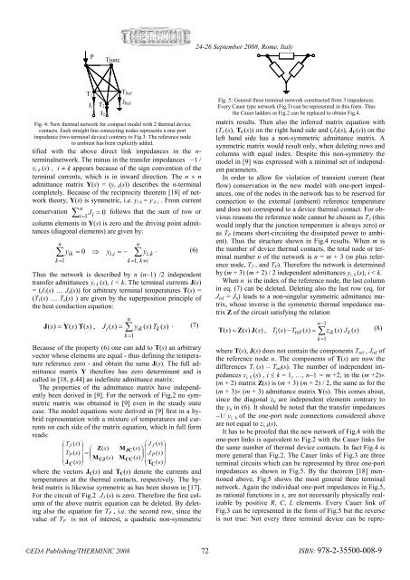
PTjunc24-26 September 2008, Rome, ItalyT 1J 1T2J 2T RefJ RefFig. 4: New thermal network for compact model with 2 thermal devicecontacts. Each straight line connecting nodes represents a one-portimpedance (two-terminal device) contrary to Fig.3. The reference nodeto ambient has been explicitly added.tified with the above direct link impedances in the n-terminalnetwork. The minus in the transfer impedances −1 /y i k (s) , i ≠ k appears because of the sign convention of theterminal currents, which is in inward direction. The n × nadmittance matrix Y(s) = (y i k (s)) describes the n-terminalcompletely. Because of the reciprocity theorem [18] of networktheory, Y(s) is symmetric, i.e. y i k = y k i . From currentnconservation ∑ =J = 0i 1 i follows that the sum of row orcolumn elements in Y(s) is zero and the driving point admittances(diagonal elements) are given by:nn∑ yik= 0 ⇒ yii = − ∑ y . (6),i,kk = 1k = 1, k ≠iThus the network is described by n (n−1) /2 independenttransfer admittances y i k (s), i < k. The terminal currents J(s)= (J 1 (s) … J n (s)) for arbitrary terminal temperatures T(s) =(T 1 (s) … T n (s) ) are given by the superposition principle ofthe heat conduction equation:J ( s)= Y(s)T(s),nJi( s)= ∑ yik( s)Tk( s). (7)k = 1Because of the property (6) one can add to T(s) an arbitraryvector whose elements are equal - thus defining the temperaturereference zero - and obtain the same J(s). The full admittancematrix Y therefore has zero determinant and iscalled in [18, p.44] an indefinite admittance matrix.The properties of the admittance matrix have independentlybeen derived in [9]. For the network of Fig.2 no symmetricmatrix was obtained in [9] even in the steady statecase. The model equations were derived in [9] first in a hybridrepresentation with a mixture of temperatures and currentson each side of the matrix equation, which in full formreads:⎛ TJ( s)⎞⎛ J J ( s)⎞⎜ ⎟ ⎛ Z(s)MJC( s)⎞ ⎜ ⎟⎜ TP( s)⎟ =⎜⎟ ⎜ J P ( s)⎟⎜ ⎟ ⎝MCJ( s)MCC( s)⎠ ⎜ ⎟⎝ JC(s)⎠⎝TC( s)⎠where the vectors J C (s) and T C (s) denote the currents andtemperatures at the thermal contacts, respectively. The hybridmatrix is likewise symmetric as has been shown in [17].For the circuit of Fig.2 J J (s) is zero. Therefore the first columnof the above matrix equation can be deleted. By deletingalso the equation for T P , i.e. the second row, since thevalue of T P is not of interest, a quadratic non-symmetricFig. 5: General three terminal network constructed from 3 impedances.Every Cauer type network (Fig.3) can be represented in this form. Thusthe Cauer ladders in Fig.2 can be replaced to obtain Fig.4.matrix results. Then also the inferred matrix equation with(T J (s), T C (s)) on the right hand side and (J P (s), J C (s)) on theleft hand side has a non-symmetric admittance matrix. Asymmetric matrix would result only, when deleting rows andcolumns with equal index. Despite this non-symmetry themodel in [9] was expressed with a minimal set of independentparameters.In order to allow for violation of transient current (heatflow) conservation in the new model with one-port impedances,one of the nodes in the network has to be reserved forconnection to the external (ambient) reference temperatureand does not correspond to a device thermal contact. For obviousreasons the reference node cannot be chosen as T J (thiswould imply that the junction temperature is always zero) oras T P (means short-circuiting the dissipated power to ambient).Thus the structure shown in Fig.4 results. When m isthe number of device thermal contacts, the total node or terminalnumber n of the network is n = m + 3 (m plus referencenode, T J , and T P ). Therefore the network is determinedby (m + 3) (m + 2) / 2 independent admittances y i, k (s), i < k.When n is the index of the reference node, the last columnin eq. (7) can be deleted. Deleting also the last row (eq. forJ ref = J n ) leads to a non-singular symmetric admittance matrix,whose inverse is the symmetric thermal impedance matrixZ of the circuit satisfying the relationn∑ − 1T ( s)= Z(s)J(s), Ti( s)− Tref ( s)= zik( s)Jk( s)(8)k = 1where T(s), J(s) does not contain the components T ref , J ref ofthe reference node n. The components of T(s) are now thedifferences T i (s) – T ref (s). The number of independent impedancesz i, k (s) , i ≤ k = 1, …, n−1 = m +2, in the (m +2)×(m + 2) matrix Z(s) is (m + 3) (m + 2) / 2, the same as for the(m + 3)× (m + 3) admittance matrix Y(s). This comes about,since the diagonal z ii are independent elements contrary tothe y ii in (6). It should be noted that the transfer impedances−1/ y i, k of the one-port node connections considered aboveare not equal to z i, k (s).It has to be proofed that the new network of Fig.4 with theone-port links is equivalent to Fig.2 with the Cauer links forthe same number of thermal device contacts. In fact Fig.4 ismore general than Fig.2. The Cauer links of Fig.3 are threeterminal circuits which can be represented by three one-portimpedances as shown in Fig.5. By the theorem [18] mentionedabove, Fig.5 shows the most general three terminalnetwork. Again the individual one-port impedances in Fig.5,as rational functions in s, are not necessarily physically realizableby positive R, C, L elements. Every Cauer link ofFig.3 can be represented in the form of Fig.5 but the reverseis not true: Not every three terminal device can be repre-©<strong>EDA</strong> <strong>Publishing</strong>/THERMINIC 2008 72ISBN: 978-2-35500-008-9


