

Online proceedings - EDA Publishing Association
Online proceedings - EDA Publishing Association
Online proceedings - EDA Publishing Association
- No tags were found...

Create successful ePaper yourself
Turn your PDF publications into a flip-book with our unique Google optimized e-Paper software.
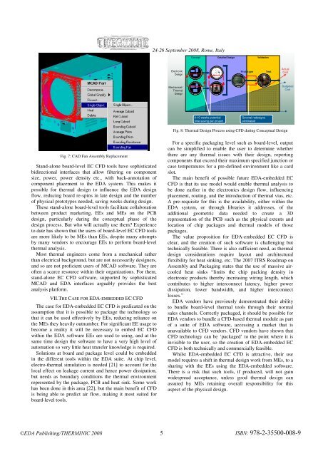
24-26 September 2008, Rome, ItalyConceptDetailed DesignValidationElectronicDesignPrototypeTestActualCostMechanical/ThermalDesignBudgetedCost8-10 weeks potentialtime saving per projectSeveral redesignseliminatedFig. 8: Thermal Design Process using CFD during Conceptual DesignFig. 7: CAD Fan Assembly ReplacementStand-alone board-level EC CFD tools have sophisticatedbidirectional interfaces that allow filtering on componentsize, power, power density etc., with back-annotation ofcomponent placement to the <strong>EDA</strong> system. This makes itpossible for thermal design to influence the <strong>EDA</strong> designflow, reducing board re-spins in late design and the numberof physical prototypes needed, saving weeks during design.These stand-alone board-level tools facilitate collaborationbetween product marketing, EEs and MEs on the PCBdesign, particularly during the conceptual phase of thedesign process. But who will actually use them? Experienceto date has shown that the users of board-level EC CFD toolsare more likely to be MEs than EEs, despite many attemptsby many vendors to encourage EEs to perform board-levelthermal analysis.Most thermal engineers come from a mechanical ratherthan electrical background, but are not necessarily designers,and so are not proficient users of MCAD software. They areoften a scarce resource within their organizations. For them,stand-alone EC CFD software, supported by sophisticatedMCAD and <strong>EDA</strong> interfaces arguably provides the bestanalysis platform.VII. THE CASE FOR <strong>EDA</strong>-EMBEDDED EC CFDThe case for <strong>EDA</strong>-embedded EC CFD is predicated on theassumption that it is possible to package the technology sothat it can be used effectively by EEs, reducing reliance onthe MEs they heavily outnumber. For significant EE usage tobecome a reality it will be necessary to embed EC CFDwithin the <strong>EDA</strong> software EEs are used to using, and at thesame time design the software to have a very high level ofautomation so very little heat transfer knowledge is required.Solutions at board and package level could be embeddedin the different tools within the <strong>EDA</strong> suite. At chip level,electro-thermal simulation is needed [21] to account for thelocal effect on leakage current and hence power dissipation,but needs as boundary conditions the thermal environmentrepresented by the package, PCB and heat sink. Some workhas been done in this area [22], but the main benefit of CFDis being able to predict air flow, making it most suited forboard-level tools.For a specific packaging level such as board-level, outputcan be simplified to enable the user to determine whetherthere are any thermal issues with their design, reportingcomponents that exceed their maximum specified junction orcase temperatures for a pre-defined environment like a cardslot.The main benefit of possible future <strong>EDA</strong>-embedded ECCFD is that its use model would enable thermal analysis tobe done earlier in the electronics design flow, influencingplacement, routing, and the introduction of thermal vias, etc.A pre-requisite for this is the availability, either within the<strong>EDA</strong> system, or through libraries it addresses, of theadditional geometric data needed to create a 3Drepresentation of the PCB such as the physical extents andlocation of chip packages and thermal models of thosepackages.The value proposition for <strong>EDA</strong>-embedded EC CFD isclear, and the creation of such software is challenging buttechnically feasible. There is also sufficient need, as thermaldesign considerations require layout and architecturalflexibility for heat sinking, etc. The 2007 ITRS Roadmap onAssembly and Packaging states that the use of massive aircooledheat sinks “limits the chip packing density inelectronic products thereby increasing wiring length, whichcontributes to higher interconnect latency, higher powerdissipation, lower bandwidth, and higher interconnectlosses.”<strong>EDA</strong> vendors have previously demonstrated their abilityto bundle board-level thermal tools through their normalsales channels. Correctly packaged, it should be possible for<strong>EDA</strong> vendors to bundle a CFD-based thermal module as partof a suite of <strong>EDA</strong> software, accessing a market that isunavailable to CFD vendors. CFD vendors have shown thatCFD technology can be ‘packaged’ to the point where it isinvisible to the user, so the creation of <strong>EDA</strong>-embedded ECCFD is both technically and commercially feasible.Whilst <strong>EDA</strong>-embedded EC CFD is attractive, their usemodel requires a shift in thermal design work from MEs, to asharing with the EEs using the <strong>EDA</strong>-embedded software.There is a risk that such tools, if produced, will not gainwidespread acceptance, unless good thermal design canassured by MEs retaining overall responsibility for thisaspect of the physical design.©<strong>EDA</strong> <strong>Publishing</strong>/THERMINIC 2008 5ISBN: 978-2-35500-008-9


