

Online proceedings - EDA Publishing Association
Online proceedings - EDA Publishing Association
Online proceedings - EDA Publishing Association
- No tags were found...

Create successful ePaper yourself
Turn your PDF publications into a flip-book with our unique Google optimized e-Paper software.
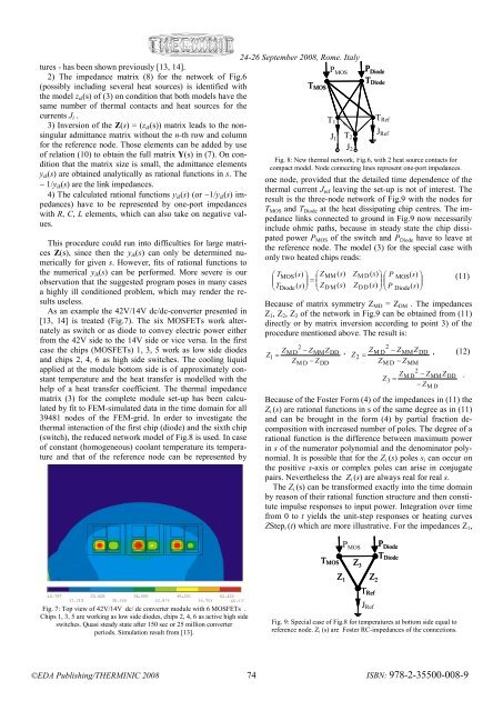
tures - has been shown previously [13, 14].2) The impedance matrix (8) for the network of Fig.6(possibly including several heat sources) is identified withthe model z ik (s) of (3) on condition that both models have thesame number of thermal contacts and heat sources for thecurrents J i .3) Inversion of the Z(s) = (z ik (s)) matrix leads to the nonsingularadmittance matrix without the n-th row and columnfor the reference node. Those elements can be added by useof relation (10) to obtain the full matrix Y(s) in (7). On conditionthat the matrix size is small, the admittance elementsy ik (s) are obtained analytically as rational functions in s. The− 1/y ik (s) are the link impedances.4) The calculated rational functions y ik (s) (or −1/y ik (s) impedances)have to be represented by one-port impedanceswith R, C, L elements, which can also take on negative values.This procedure could run into difficulties for large matricesZ(s), since then the y ik (s) can only be determined numericallyfor given s. However, fits of rational functions tothe numerical y ik (s) can be performed. More severe is ourobservation that the suggested program poses in many casesa highly ill conditioned problem, which may render the resultsuseless.As an example the 42V/14V dc/dc-converter presented in[13, 14] is treated (Fig.7). The six MOSFETs work alternatelyas switch or as diode to convey electric power eitherfrom the 42V side to the 14V side or vice versa. In the firstcase the chips (MOSFETs) 1, 3, 5 work as low side diodesand chips 2, 4, 6 as high side switches. The cooling liquidapplied at the module bottom side is of approximately constanttemperature and the heat transfer is modelled with thehelp of a heat transfer coefficient. The thermal impedancematrix (3) for the complete module set-up has been calculatedby fit to FEM-simulated data in the time domain for all39481 nodes of the FEM-grid. In order to investigate thethermal interaction of the first chip (diode) and the sixth chip(switch), the reduced network model of Fig.8 is used. In caseof constant (homogeneous) coolant temperature its temperatureand that of the reference node can be represented by24-26 September 2008, Rome, ItalyT MOSP MOST 1J 1Fig. 8: New thermal network, Fig.6, with 2 heat source contacts forcompact model. Node connecting lines represent one-port impedances.one node, provided that the detailed time dependence of thethermal current J ref leaving the set-up is not of interest. Theresult is the three-node network of Fig.9 with the nodes forT MOS and T Diode at the heat dissipating chip centres. The impedancelinks connected to ground in Fig.9 now necessarilyinclude ohmic paths, because in steady state the chip dissipatedpower P MOS of the switch and P Diode have to leave atthe reference node. The model (3) for the special case withonly two heated chips reads:⎛ T MOS(s)⎞ ⎛ ZMM( s)ZM D ( s)⎞ ⎛ P ⎞= ⎜⎟ MOS(s)⎜⎟⎜⎟ (11)⎝TDiode( s)⎠ ⎝ZD M ( s)ZD D ( s)⎠ ⎝ P Diode(s)⎠Because of matrix symmetry Z MD = Z DM . The impedancesZ 1 , Z 2 , Z 3 of the network in Fig.9 can be obtained from (11)directly or by matrix inversion according to point 3) of theprocedure mentioned above. The result is:2ZM D − ZMMZZDD1 = ,ZM D − ZDDT2J 2Z2P DiodeT DiodeT RefJ Ref2ZM D − ZMMZDDZM D − ZMM2ZM D − ZMMZZDD3 =− ZM D= , (12)Because of the Foster Form (4) of the impedances in (11) theZ i (s) are rational functions in s of the same degree as in (11)and can be brought in the form (4) by partial fraction decompositionwith increased number of poles. The degree of arational function is the difference between maximum powerin s of the numerator polynomial and the denominator polynomial.It is possible that for the Z i (s) poles s i can occur onthe positive s-axis or complex poles can arise in conjugatepairs. Nevertheless the Z i (s) are always real for real s.The Z i (s) can be transformed exactly into the time domainby reason of their rational function structure and then constituteimpulse responses to input power. Integration over timefrom 0 to t yields the unit-step responses or heating curvesZStep i (t) which are more illustrative. For the impedances Z 1 ,.P MOS T RefP DiodeT MOSZ 3Z 1Z 2T DiodeFig. 7: Top view of 42V/14V dc/ dc converter module with 6 MOSFETs .Chips 1, 3, 5 are working as low side diodes, chips 2, 4, 6 as active high sideswitches. Quasi steady state after 150 sec or 25 million converterperiods. Simulation result from [13].J RefFig. 9: Special case of Fig.8 for temperatures at bottom side equal toreference node. Z i (s) are Foster RC-impedances of the connections.©<strong>EDA</strong> <strong>Publishing</strong>/THERMINIC 2008 74ISBN: 978-2-35500-008-9


