

Online proceedings - EDA Publishing Association
Online proceedings - EDA Publishing Association
Online proceedings - EDA Publishing Association
- No tags were found...

You also want an ePaper? Increase the reach of your titles
YUMPU automatically turns print PDFs into web optimized ePapers that Google loves.
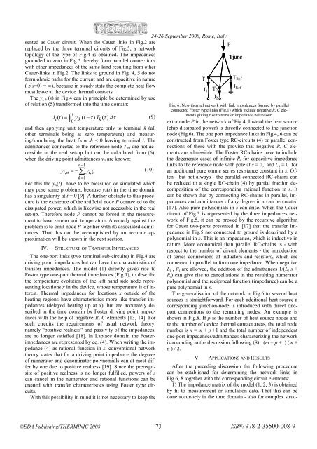
sented as Cauer circuit. When the Cauer links in Fig.2 arereplaced by the three terminal circuits of Fig.5, a networktopology of the type of Fig.4 is obtained. The impedancesgrounded to zero in Fig.5 thereby form parallel connectionswith other impedances of the same kind resulting from otherCauer-links in Fig.2. The links to ground in Fig. 4, 5 do notform ohmic paths for the current and are capacitive in nature( z(s=0) = ∞), because in steady state the complete heat flowmust leave at the device thermal contacts.The y i, k (s) in Fig.4 can in principle be determined by useof relation (5) transformed into the time domain:tJi ( t)= ∫ yik( t −τ) Tk( τ ) dτ(9)0and then applying unit temperature only to terminal k (allother terminals being at zero temperature) and measuring/simulatingthe heat flow J i < 0 leaving terminal i. Theadmittances connected to the reference node T ref are not accessiblein the real set-up but can be calculated from (6),when the driving point admittances y ii are known:n= −∑ − 1y i,n y(10)i,kk = 1For this the y ii (t) have to be measured or simulated whichmay pose some problems, because y ii (t) in the time domainhas a singularity at t = 0 [9]. A further obstacle to this procedureis the existence of the artificial node P connected to thedissipated power, which is likewise not accessible in the realset-up. Therefore node P cannot be forced in the measurementto have zero or unit temperature. A remedy against thisproblem is to omit node P together with its associated admittances.That this can be accomplished by an accurate approximationwill be shown in the next section.IV. STRUCTURE OF TRANSFER IMP<strong>EDA</strong>NCESThe one-port links (two terminal sub-circuits) in Fig.4 aredriving point impedances but can have the characteristics oftransfer impedances. The model (1) directly gives rise toFoster type one-port thermal impedances (Fig.1), to describethe temperature evolution of the left hand side node representinglocations x in the device, whose temperature is of interest.Thermal impedances for locations x outside of theheating regions have characteristics more like transfer impedances(delayed heating up at x), but are accurately describedin the time domain by Foster driving point impedanceswith the help of negative R, C elements [13, 14]. Forsuch circuits the requirements of usual network theory,namely “positive realness” and passivity of the impedances,are no longer satisfied [18]. In Laplace domain the Fosterimpedancesare represented by eq. (4). When writing the impedance(4) as rational function in s, conventional networktheory states that for a driving point impedance the degreesof numerator and denominator polynomials can at most differby one due to positive realness [19]. Since the prerequisiteof positive realness is no longer fulfilled, powers of scan cancel in the numerator and rational functions can becreated with transfer characteristics using Foster type circuits.With this possibility in mind it is not necessary to keep the24-26 September 2008, Rome, ItalyPT 1J 1T2J 2TjuncT RefJ RefFig. 6: New thermal network with link impedances formed by parallelconnected Foster type links (Fig.1) which include negative R, C elementsgiving rise to transfer impedance behaviour.extra node P in the network of Fig.4. Instead the heat source(chip dissipated power) is directly connected to the junctionnode (Fig.6). The one port impedance links in Fig.4, 6 can beconstructed from Foster type RC-circuits (4) or parallel connectionsof these with the proviso that negative R, C elementsare admissible. The Foster RC-chains have to includethe degenerate cases of infinite R i for capacitive impedancelinks to the reference node with pole at s = 0, and C i = 0 foran additional pure ohmic series resistance constant in s. Often- but not always - the parallel connected RC-chains canbe reduced to a single RC-chain (4) by partial fraction decompositionof the corresponding rational function in s. Itcan be shown that by connecting RC-chains in parallel, impedancesand admittances of any degree in s can be created[17]. Also pure polynomials in s can arise. When the Cauercircuit of Fig.3 is represented by the three impedances networkof Fig.5, it can be proved by the recursive algorithmfor Cauer two-ports presented in [17] that the transfer impedancein Fig.5 not connected to ground is described by apolynomial in s. This is an impedance, which is inductive innature. More economical than parallel RC-chains is - withrespect to the number of circuit elements - the introductionof series connections of inductors and resistors, which areconnected in parallel to form one impedance. When negativeL i , R i are allowed, the addition of the admittances 1/(L i s +R i ) can give rise to cancellations in the resulting numeratorpolynomial and the reciprocal function (impedance) can be apure polynomial in s.The generalisation of the network in Fig.6 to several heatsources is straightforward. For each additional heat source acorresponding junction-node is introduced with direct oneportconnections to the remaining nodes. An example isshown in Fig.8. If p is the number of heat source nodes andm the number of device thermal contact areas, the total nodenumber is n = m + p +1 and the total number of independentone-port impedances/admittances characterizing the networkis according to the discussion following (8): (m + p +1) (m +p ) / 2.V. APPLICATIONS AND RESULTSAfter the preceding discussion the following procedurecan be established for determining the network links inFig.6, 8 together with the corresponding circuit elements:1) The impedance matrix of the model (1, 2, 3) is obtainedby fit to measurement or simulation data. That this can bedone accurately in the time domain - also for complex struc-©<strong>EDA</strong> <strong>Publishing</strong>/THERMINIC 2008 73ISBN: 978-2-35500-008-9


