
Create successful ePaper yourself
Turn your PDF publications into a flip-book with our unique Google optimized e-Paper software.
3. Technical data<br />
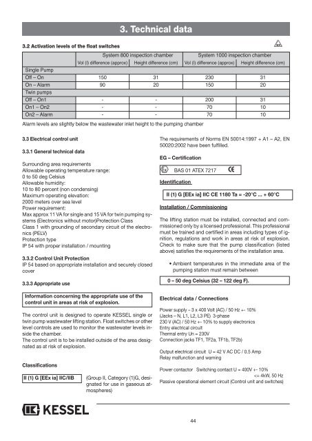
3.2 Activation levels of the float switches<br />
EX<br />
System 800 inspection chamber<br />
System 1000 inspection chamber<br />
Vol (l) difference (approx) Height difference (cm) Vol (l) difference (approx) Height difference (cm)<br />
Single Pump<br />
Off – On 150 31 230 31<br />
On – Alarm 90 20 150 20<br />
Twin pumps<br />
Off – On1 - - 200 31<br />
On1 – On2 - - 70 10<br />
On2 – Alarm - - 70 10<br />
Alarm levels are slightly below the wastewater inlet height to the pumping chamber<br />
3.3 Electrical control unit<br />
3.3.1 General technical data<br />
Surrounding area requirements<br />
Allowable operating temperature range:<br />
0 to 50 deg Celsius<br />
Allowable humidity:<br />
10 to 80 percent (non condensing)<br />
Maximum operating elevation:<br />
2000 meters over sea level<br />
Power requirement:<br />
Max approx 11 VA for single and 15 VA for twin pumping systems<br />
(Electronics without motor)Protection Class<br />
Class 1 with grounding of secondary circuit of the electronics<br />
(PELV)<br />
Protection type<br />
IP 54 with proper installation / mounting<br />
3.3.2 Control Unit Protection<br />
IP 54 based on appropriate installation and securely closed<br />
cover<br />
3.3.3 Appropriate use<br />
Information concerning the appropriate use of the<br />
control unit in areas at risk of explosion.<br />
The control unit is designed to operate KESSEL single or<br />
twin pump wastewater lifting station. Float switches or other<br />
level controls are used to monitor the wastewater levels inside<br />
the chamber.<br />
The control unit is to be installed outside of the area designated<br />
as at risk of explosion.<br />
Classifications<br />
II (1) G [EEx ia] IIC/IIB<br />
(Group II, Category (1)G, designated<br />
for use in gaseous atmospheres)<br />
The requirements of Norms EN 50014:1997 + A1 – A2, EN<br />
50020:2002 have been fulfilled.<br />
EG – Certification<br />
BAS 01 ATEX 7217<br />
Identification<br />
II (1) G [EEx ia] IIC CE 1180 Ta = -20°C ... + 60°C<br />
Installation / Commissioning<br />
The lifting station must be installed, connected and commissioned<br />
only by a licensed professional. This professional<br />
must be trained and certified in areas including types of ignition,<br />
regulations and work in areas at risk of explosion.<br />
Check to make sure that the pump classification (listed<br />
above) satisfies the requirements of the installation area.<br />
• Ambient temperatures in the immediate area of the<br />
pumping station must remain between<br />
0 – 50 deg Celsius (32 – 122 deg F).<br />
Electrical data / Connections<br />
Power supply – 3 x 400 Volt (AC) / 50 Hz +- 10%<br />
(Jacks – N, L1, L2, L3 PE) 3-phase<br />
230 V (AC) / 50 Hz +- 10% to supply electronics<br />
Entry electrical circuit<br />
Thermal entry Un = 230V<br />
Connection jacks TF1, TF2a, TF1b, TF2b)<br />
Output electrical circuit U = 42 V AC DC / 0.5 Amp<br />
Relay malfunction and warning<br />
Power contactor Switching contact U = 400V +- 10%<br />