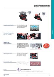

Create successful ePaper yourself
Turn your PDF publications into a flip-book with our unique Google optimized e-Paper software.
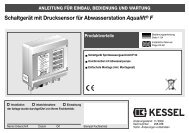
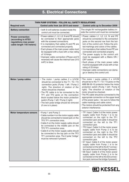
5. Electrical Connections<br />
TWIN PUMP SYSTEMS – FOLLOW ALL SAFETY REGULATIONS!<br />
Required work Control units from Jan 2010 and newer Control units up to December 20<strong>09</strong><br />
Battery connection<br />
Power connection<br />
(according to ATEX<br />
regulations max power<br />
cable length 140 meters)<br />
• both 9-volt batteries located inside the<br />
control unit must be connected.<br />
• Power cables L1, L2, L3, N and PE should<br />
be connected to their appropriate jacks<br />
with the screwed connections.<br />
• It is mandatory that cables N and PE are<br />
connected and connected properly.<br />
• Each phase of the main power cable must<br />
be equipped with a fuse with a max rating<br />
of 16 Amps<br />
• Improper cable connection (Phase and N<br />
reversed) will cause the internal fuse (315<br />
mAT) to blow.<br />
The single 9V rechargeable battery inside<br />
the control unit must be connected<br />
• Power cables L1, L2, L3, N and PE<br />
should be connected to the connection<br />
jacks on the second row from the bottom<br />
of the control unit. Follow the printed<br />
markings and colors of the cables.<br />
• It is mandatory that cables N and PE are<br />
connected and connected properly.<br />
• The power supply to the control unit<br />
must be equipped with a Mains ON /<br />
OFF switch.<br />
• Each phase of the main power cable<br />
must be equipped with a fuse with a max<br />
rating of 25 Amps<br />
• Improper cable connections can damage<br />
or destroy the control unit.<br />
Motor / pump cables<br />
• The motor / pump cables 2 x U/V/W<br />
should be connected to the T1 / T2 / T3<br />
connection jacks (Pump 1 left / Pump 2<br />
right). The direction of rotation of the<br />
motor should be checked.<br />
• The PE cable is to be connected to the<br />
TF1 and TF2 jacks on the connection<br />
block located below the motor protection<br />
switch (Pump 1 left / Pump 2 right)<br />
• The twin polar bridge should be removed<br />
(if one is in place)<br />
• The motor / pump cables 2 x U/V/W<br />
should be to the T1 / T2 / T3 jacks on the<br />
ABB B6-30-10 protector below the motor<br />
protection switch (Pump 1 left / Pump 2<br />
right). The direction of rotation of the<br />
motor should be checked.<br />
• The PE cable should be connected to the<br />
appropriate connection on the upper level<br />
of the power jacks – be sure to follow the<br />
cable markings and cable colors.<br />
• The motors should be protected from any<br />
exterior interference.<br />
Motor temperature sensors • Pump 1 and Pump 2<br />
• Cable number 4 on the motor supply cable<br />
should be connected to lowest jack on the<br />
TF2 TF1 connection area.<br />
• Cable 5 on the motor supply cable should<br />
be connected to the middle jack on the<br />
TF2 TF1 connection area.<br />
• Cable 6 on the motor supply cable should<br />
be connected to the top jack on the TF2<br />
TF1 connection area. The 2 polar ‘bridge’<br />
must be removed if present.<br />
• TF1 Input: Cable 5 of the motor power<br />
supply cable from Pump 1 is to be<br />
connected on the right to the TF1<br />
connection jack and cable 4 should be<br />
connected on the left to the TF1<br />
connection jack.<br />
• TF2 Input: Cable 5 of the motor power<br />
supply cable from Pump 2 is to be<br />
connected on the right to the TF2<br />
connection jack and cable 4 should be<br />
connected on the left to the TF2<br />
connection jack.<br />
• E7 Input: Cable 6 of the motor power<br />
supply cable from Pump 1 is to be<br />
connected on the left to the E7 connection<br />
jack (remove the bridge if present).<br />
• E8 Input: Cable 6 of the motor power<br />
supply cable from Pump 2 is to be<br />
connected on the left to the E8 connection<br />
jack (remove the bridge if present).<br />
55