
You also want an ePaper? Increase the reach of your titles
YUMPU automatically turns print PDFs into web optimized ePapers that Google loves.
4. Installation<br />
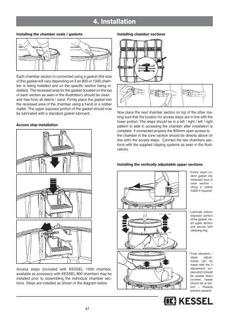
Installing the chamber seals / gaskets<br />
Installing chamber sections<br />
Each chamber section is connected using a gasket (the size<br />
of this gasket will vary depending on if an 800 or 1000 chamber<br />
is being installed and on the specific section being installed).<br />
The recessed area for the gasket (located on the top<br />
of each section as seen in the illustration) should be clean<br />
and free from all debris / sand. Firmly place the gasket into<br />
the recessed area of the chamber using a hand or a rubber<br />
mallet. The upper exposed portion of the gasket should now<br />
be lubricated with a standard gasket lubricant..<br />
Access step installation<br />
Now place the next chamber section on top of the other making<br />
sure that the location for access steps are in line with the<br />
lower portion. The steps should be in a left / right / left / right<br />
pattern to aide in accessing the chamber after installation is<br />
complete. If connected properly the 600mm open access to<br />
the chamber in the cone section should be directly above (in<br />
line with) the access steps. Connect the two chambers sections<br />
with the supplied clipping systems as seen in the illustrations.<br />
Installing the vertically adjustable upper sections<br />
• Firmly insert custom<br />
gasket into<br />
recessed area of<br />
cone section -<br />
using a rubber<br />
mallet if required<br />
• Lubricate interior<br />
exposed portion<br />
of the gasket, insert<br />
upper section<br />
and secure with<br />
clamping ring.<br />
Access steps (included with KESSEL 1000 chamber,<br />
available as accessory with KESSEL 800 chamber) may be<br />
installed prior to assembling the individual chamber sections.<br />
Steps are installed as shown in the diagram below.<br />
• Final elevation /<br />
slope adjustments<br />
can be<br />
made with the 3<br />
adjustment screws<br />
which should<br />
be upside down<br />
(screws heads<br />
should be at bottom<br />
– threads<br />
pointed upward)<br />
47