
Create successful ePaper yourself
Turn your PDF publications into a flip-book with our unique Google optimized e-Paper software.
4. Installation<br />
The delivered shipment should include the following (see<br />
section 2.2):<br />
- KESSEL Inspection Chamber delivered in sections<br />
(for assembly on-site)<br />
- Sewage pump(s)<br />
- Electrical Control Unit<br />
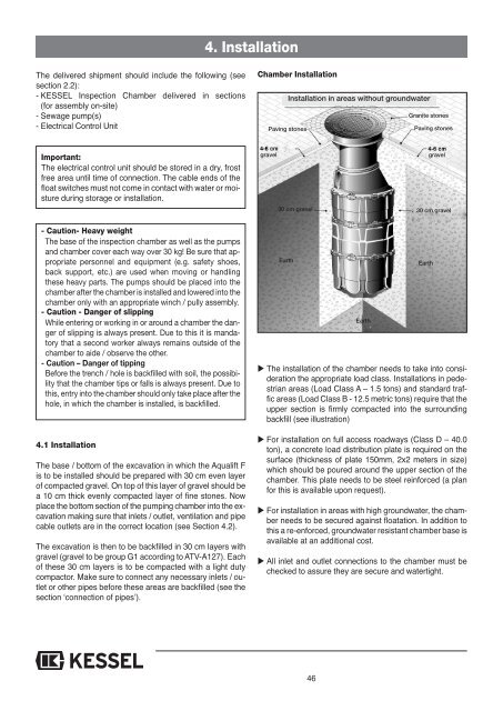
Chamber Installation<br />
Installation in areas without groundwater<br />
Granite stones<br />
Paving stones<br />
Paving stones<br />
Important:<br />
The electrical control unit should be stored in a dry, frost<br />
free area until time of connection. The cable ends of the<br />
float switches must not come in contact with water or moisture<br />
during storage or installation.<br />
gravel<br />
30 cm gravel<br />
gravel<br />
30 cm gravel<br />
- Caution- Heavy weight<br />
The base of the inspection chamber as well as the pumps<br />
and chamber cover each way over 30 kg! Be sure that appropriate<br />
personnel and equipment (e.g. safety shoes,<br />
back support, etc.) are used when moving or handling<br />
these heavy parts. The pumps should be placed into the<br />
chamber after the chamber is installed and lowered into the<br />
chamber only with an appropriate winch / pully assembly.<br />
- Caution - Danger of slipping<br />
While entering or working in or around a chamber the danger<br />
of slipping is always present. Due to this it is mandatory<br />
that a second worker always remains outside of the<br />
chamber to aide / observe the other.<br />
- Caution – Danger of tipping<br />
Before the trench / hole is backfilled with soil, the possibility<br />
that the chamber tips or falls is always present. Due to<br />
this, entry into the chamber should only take place after the<br />
hole, in which the chamber is installed, is backfilled.<br />
4.1 Installation<br />
The base / bottom of the excavation in which the Aqualift F<br />
is to be installed should be prepared with 30 cm even layer<br />
of compacted gravel. On top of this layer of gravel should be<br />
a 10 cm thick evenly compacted layer of fine stones. Now<br />
place the bottom section of the pumping chamber into the excavation<br />
making sure that inlets / outlet, ventilation and pipe<br />
cable outlets are in the correct location (see Section 4.2).<br />
The excavation is then to be backfilled in 30 cm layers with<br />
gravel (gravel to be group G1 according to ATV-A127). Each<br />
of these 30 cm layers is to be compacted with a light duty<br />
compactor. Make sure to connect any necessary inlets / outlet<br />
or other pipes before these areas are backfilled (see the<br />
section ‘connection of pipes’).<br />
Earth<br />
Earth<br />
Earth<br />
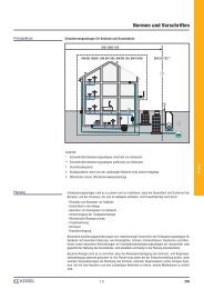
The installation of the chamber needs to take into consideration<br />
the appropriate load class. Installations in pedestrian<br />
areas (Load Class A – 1.5 tons) and standard traffic<br />
areas (Load Class B - 12.5 metric tons) require that the<br />
upper section is firmly compacted into the surrounding<br />
backfill (see illustration)<br />
For installation on full access roadways (Class D – 40.0<br />
ton), a concrete load distribution plate is required on the<br />
surface (thickness of plate 150mm, 2x2 meters in size)<br />
which should be poured around the upper section of the<br />
chamber. This plate needs to be steel reinforced (a plan<br />
for this is available upon request).<br />
For installation in areas with high groundwater, the chamber<br />
needs to be secured against floatation. In addition to<br />
this a re-enforced, groundwater resistant chamber base is<br />
available at an additional cost.<br />
All inlet and outlet connections to the chamber must be<br />
checked to assure they are secure and watertight.<br />
46