
Create successful ePaper yourself
Turn your PDF publications into a flip-book with our unique Google optimized e-Paper software.
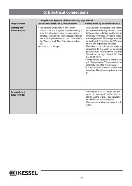
5. Electrical connections<br />
Single Pump Systems – Follow all safety regulations!<br />
Required work Control units from Jan 2010 and newer Control units up to December 20<strong>09</strong><br />
Warning and<br />
Alarm outputs<br />
• The ‘Störung’ (malfunction) and ‘Alarm’<br />
(alarm) control unit signals are controlled by a<br />
relay. Inductive loads must be externally eliminated.<br />
The stand by (powerless) position of<br />
the relays is printed on the board. This means<br />
the ‘Warning’ and ‘Alarm’ signals are activated<br />
• 42 V ac dc / 0.5 Amps<br />
• The ‘Störung’ (malfunction) and ‘Alarm’<br />
(alarm) control unit signals are controlled<br />
by a relay. Inductive loads must be<br />
externally eliminated. The stand by (powerless)<br />
position of the relays is printed<br />
on the board. This means the ‘Warning’<br />
and ‘Alarm’ signals are activated<br />
• The relay contacts have absolutely no<br />
connection to the supply or operating<br />
power and are separated from this up to<br />
300 volts according to Table D.10 of the<br />
EN 61010 norm<br />
• The relays are designed to switch a 250<br />
volt / 2 Amp source. The current is to be<br />
externally limited to these values.<br />
• It is not allowed to switch phases with<br />
the relays. The phase may deviate from<br />
L1.<br />
Outputs L1 / N<br />
(230V / 50 Hz)<br />
•<br />
• The outputs N / L1 (2 each) are designed<br />
to activated malfunction or<br />
alarms via the relays. They should not<br />
be used for any other purpose.<br />
• The maximum allowable current is 2<br />
Amps.<br />
54