
Create successful ePaper yourself
Turn your PDF publications into a flip-book with our unique Google optimized e-Paper software.
5. Electrical connections<br />
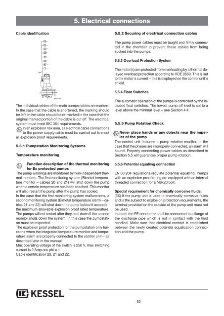
Cable identification<br />
5.5.2 Securing of electrical connection cables<br />
The pump power cables must be taught and firmly connected<br />
in the chamber to prevent these cables from being<br />
sucked into the pumps.<br />
5.5.3 Overload Protection System<br />
The motor(s) are protected from overloading by a thermal delayed<br />
overload protection according to VDE 0660. This is set<br />
to the motor´s current – this is displayed on the control unit´s<br />
shield.<br />
5.5.4 Float Switches<br />
The individual cables of the main pumps cables are marked.<br />
In the case that the cable is shortened, the marking should<br />
be left or the cable should be re-marked in the case that the<br />
original marked portion of the cable is cut off. The electrical<br />
system must meet IEC 364 requirements.<br />
In an explosion risk area, all electrical cable connections<br />
to the power supply cable must be carried out to meet<br />
all explosion proof requirements.<br />
5.5.1 Pumpstation Monitoring Systems<br />
Temperature monitoring<br />
Function description of the thermal monitoring<br />
for Ex protected pumps<br />
The pump windings are monitored by twin independent thermal<br />
monitors. The first monitoring system (Bimetal temperature<br />
monitor – cables 20 and 21) will shut down the pump<br />
when a certain temperature has been reached. This monitor<br />
will also restart the pump after the pump has cooled.<br />
In the case that the first monitoring system malfunctions, a<br />
second monitoring system (Bimetal temperature alarm – cables<br />
21 and 22) will shut down the pump before it exceeds<br />
the maximum allowable explosion proof rated temperature.<br />
The pumps will not restart after they cool down if the second<br />
monitor shuts down the system. In this case the pumpstation<br />
must be inspected.<br />
The explosion proof protection for the pumpstation only functions<br />
when the integrated temperature monitor and temperature<br />
alarm are properly connected to the control unit – as<br />
described later in the manual.<br />
Max operating voltage of the switch is 250 V, max switching<br />
current is 2 Amp cos phi = 1<br />
Cable identification 20, 21 and 22.<br />
The automatic operation of the pumps is controlled by the included<br />
float switches. The lowest pump off level is set to a<br />
level above the minimal level – see Section 4.4.<br />
5.5.5 Pump Rotation Check<br />
Never place hands or any objects near the impeller<br />
of the pump<br />
The control unit includes a pump rotation monitor. In the<br />
case that the phases are improperly connected, an alarm will<br />
sound. Properly connecting power cables as described in<br />
Section 5.5 will guarantee proper pump rotation.<br />
5.5.6 Potential equalling connection<br />
EN 60 204 regulations regulate potential equalling. Pumps<br />
with an explosion proof rating are equipped with an internal<br />
threaded connection for a M8x20 bolt.<br />
Special requirement for chemically corrosive fluids:<br />
(EX) If the pump unit is used in chemically corrosive fluids<br />
and is the subject to explosion protection requirements, the<br />
terminal provided on the outside of the pump unit must not<br />
be used.<br />
Instead, the PE conductor shall be connected to a flange of<br />
the discharge pipe which is not in contact with the fluid<br />
handled. Make sure that electrical contact is established<br />
between the newly created potential equalization connection<br />
and the pump.<br />
52