
You also want an ePaper? Increase the reach of your titles
YUMPU automatically turns print PDFs into web optimized ePapers that Google loves.
5. Electrical connections<br />
NOTICE – only certified licensed professionals<br />
should conduct the following electrical connections.<br />
5.1 General instructions<br />
Before any cables are connected to the control unit, first the<br />
cable inlet plugs at the base of the control unit need to be removed<br />
and replaced with the special cable seal plugs / screws.<br />
The control unit for the Pumpstation Aqualift F must be<br />
connected to a separate main switch so that if required the<br />
entire system can be switched off. This main switch should<br />
be clearly visible and located in the immediate vicinity of the<br />
control unit. All cables entering the control unit must be secured<br />
to the control unit using the supplied plastic strain relief<br />
nuts. Cable inlet openings into the control unit which are<br />
not used must be properly closed.<br />
Important:<br />
All electrical cables must be properly secured (with tie<br />
wraps for example) so that in the case that the cable releases<br />
from the control unit that the bare ends of the cables<br />
do not come in contact with any other cables (for example<br />
in the case that cable L1 comes out of the input<br />
jacks it will physically be impossible for this cable to<br />
contact the PELV or the EX switching portion of the control<br />
unit).<br />
All local and national safety regulation should be followed. If<br />
these codes are not strictly followed, a danger to people and<br />
maintenance workers could exist. After any work on the control<br />
unit has been completed, the see-thru cover must be properly<br />
secured in order that the control unit remains splash<br />
proof.<br />
Float switch cables should be run separately from the pump<br />
power cables and main power cables in order to prevent electrical<br />
interference which could negatively affect operation<br />
of the system<br />
5.2 Mounting of control unit<br />
The control unit for this pumping station is to be installed in<br />
a frost-free, dry and well-ventilated area. The control unit<br />
may not be installed in an explosion endangered area. To<br />
prevent overheating of the inside of the control unit, sufficient<br />
air circulation in the immediate vicinity of the control unit<br />
should be provided. The control unit is to be installed vertically<br />
on a solid wall with the supplied 4 screws – a template<br />
is provided to aid in drilling holes in the wall. To access the<br />
control unit mounting screws first remove the see-thru cover.<br />
The cables for the pump(s) and the float switches should be<br />
run through an conduit pipe to the control unit. To connect<br />
these cables please follow the instructions in Section 5.4 “Installation<br />
– Cable connections”.<br />
5.3 Information concerning explosion protection<br />
Only the float switches can be installed in the explosion risk<br />
areas. When connected cables inside the control unit make<br />
sure that the cables are connected to their appropriate jacks.<br />
Float switch cables must be connected to the float switch<br />
jacks and power and pump cables must be connected to their<br />
appropriate jacks. Improper connection of cables could damage<br />
the system as well as nullify the explosion proof rating<br />
of the system. No external power may be supplied to the float<br />
switch Off, On, On1/On2 or alarm connection jacks. As required<br />
by the connection plan, the float switch cables should<br />
only be connected to the connection jacks on the HAZARD<br />
section inside the control unit which is connected to the electrically<br />
shielded / protected control unit area.<br />
5.4 Installation – Cable connection<br />
The cables for the pump(s) and the float switches are 10 meters<br />
in length. The cables between pumping station and building<br />
must be run in a dedicated conduit pipe (as discussed<br />
in Chapter 4.2 – Pipe Connections). In the case that the 10<br />
meter cable lengths are not sufficient, the cables may be extending<br />
following VDE codes up to a maximum length of 30<br />
meters using appropriate waterproof extension connections.<br />
Contact KESSEL customer service if lengths over 30 meters<br />
are required.<br />
Important:<br />
All electrical cables must be installed so that they do not<br />
come in contact with the intake impellers of the pump(s)<br />
and are clear of the access steps as well as not hindering<br />
access to the chamber. The cable lengths must also assure<br />
that the removal of one or both of the submersible<br />
pumps for inspection and / or maintenance purposes is<br />
possible.<br />
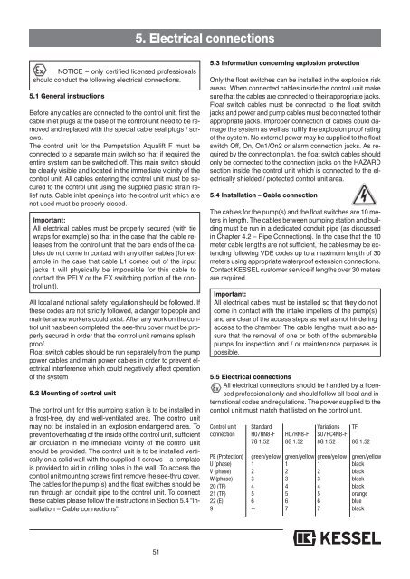
5.5 Electrical connections<br />
All electrical connections should be handled by a licensed<br />
professional only and should follow all local and international<br />
codes and regulations. The power supplied to the<br />
control unit must match that listed on the control unit.<br />
Control unit Standard Variations TF<br />
connection H07RN8-F H07RN8-F S07RC4N8-F<br />
7G 1.52 8G 1.52 8G 1.52 8G 1.52<br />
PE (Protection) green/yellow green/yellow green/yellow green/yellow<br />
U (phase) 1 1 1 black<br />
V (phase) 2 2 2 black<br />
W (phase) 3 3 3 black<br />
20 (TF) 4 4 4 black<br />
21 (TF) 5 5 5 orange<br />
22 (E) 6 6 6 blue<br />
9 -- 7 7 black<br />
51