
Create successful ePaper yourself
Turn your PDF publications into a flip-book with our unique Google optimized e-Paper software.
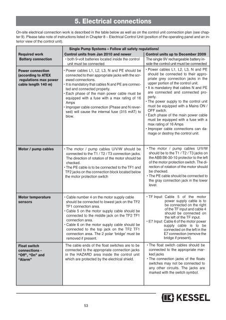
5. Electrical connections<br />
On-site electrical connection work is described in the table below as well as on the control unit connection plan (see chapter<br />
9). Please take note of instructions listed in Chapter 8 – Electrical Control Unit (position of the operating panel and an interior<br />
view of the control unit).<br />
Single Pump Systems – Follow all safety regulations!<br />
Required work Control units from Jan 2010 and newer Control units up to December 20<strong>09</strong><br />
Battery connection • both 9-volt batteries located inside the control The single 9V rechargeable battery inside<br />
unit must be connected<br />
the control unit must be connected<br />
Power connection<br />
(according to ATEX<br />
regulations max power<br />
cable length 140 m)<br />
• Power cables L1, L2, L3, N and PE should be<br />
connected to their appropriate jacks with the screwed<br />
connections.<br />
• It is mandatory that cables N and PE are connected<br />
and connected properly.<br />
• Each phase of the main power cable must be<br />
equipped with a fuse with a max rating of 16<br />
Amps<br />
• Improper cable connection (Phase and N reversed)<br />
will cause the internal fuse (315 mAT) to<br />
blow.<br />
• Power cables L1, L2, L3, N and PE<br />
should be connected to their appropriate<br />
grey connection jacks in the<br />
upper portion of the control unit.<br />
• It is mandatory that cables N and PE<br />
are connected and connected properly.<br />
• The power supply to the control unit<br />
must be equipped with a Mains ON /<br />
OFF switch.<br />
• Each phase of the main power cable<br />
must be equipped with a fuse with a<br />
max rating of 16 Amps<br />
• Improper cable connections can damage<br />
or destroy the control unit.<br />
Motor / pump cables<br />
• The motor / pump cables U/V/W should be<br />
connected to the T1 / T2 / T3 connection jacks.<br />
The direction of rotation of the motor should be<br />
checked.<br />
• The PE cable is to be connected to the TF1 and<br />
TF2 jacks on the connection block located below<br />
the motor protection switch<br />
• The motor / pump cables U/V/W<br />
should be to the T1 / T2 / T3 jacks on<br />
the ABB B6-30-10 protector to the left<br />
of the motor protection switch. The direction<br />
of rotation of the motor should<br />
be checked.<br />
• The PE cable should be connected to<br />
the gray connection jack in the lower<br />
level.<br />
Motor temperature<br />
sensors<br />
Float switch<br />
connections -<br />
“Off”, “On” and<br />
“Alarm”<br />
• Cable number 4 on the motor supply cable<br />
should be connected to lowest jack on the TF2<br />
TF1 connection area.<br />
• Cable 5 on the motor supply cable should be<br />
connected to the middle jack on the TF2 TF1<br />
connection area.<br />
• Cable 6 on the motor supply cable should be<br />
connected to the top jack on the TF2 TF1<br />
connection area. The 2 polar ‘bridge’ must be<br />
removed if present.<br />
The cable ends of the float switches are to be<br />
connected to the appropriate connection jacks<br />
in the HAZARD area inside the control unit<br />
which are protected by the electrical shield.<br />
• TF Input: Cable 5 of the motor<br />
power supply cable is to<br />
be connected on the right<br />
of the TF input and cable 4<br />
should be connected on<br />
the left of the TF input.<br />
• E7 Input: Cable 6 of the motor power<br />
supply cable is to be<br />
connected on the left in the<br />
E7 connection (remove the<br />
bridge if present).<br />
• The float switch cables should be<br />
connected to the appropriate marked<br />
jacks<br />
• The connection jacks of the floats<br />
switches may not be connected to<br />
any other circuits. The jacks are<br />
marked with the switch symbol.<br />
53