- Page 1 and 2:
MASTER CATALOG CAMSHAF TS • VALVE
- Page 3 and 4:
How to Use This Catalog About the C
- Page 5 and 6:
Table of Contents Timing Chains and
- Page 7 and 8:
Crane Cams History Crane Cams Histo
- Page 9 and 10:
Camshaft Table of Contents Chrysler
- Page 11 and 12:
Crane Camshaft Series Crane Camshaf
- Page 13 and 14:
Crane Cams & Valve Train Products S
- Page 15 and 16:
Crane Cams & Valve Train Products S
- Page 17 and 18:
Crane Cams & Valve Train Products S
- Page 19 and 20:
Duration@ .050” Advertised Durati
- Page 21 and 22:
Duration@ .050” Advertised Durati
- Page 23 and 24:
Duration@ .050” Advertised Durati
- Page 25 and 26:
Duration@ .050” Advertised Durati
- Page 27 and 28:
Duration@ .050” Advertised Durati
- Page 29 and 30:
Duration@ .050” Advertised Durati
- Page 31 and 32:
Duration@ .050” Advertised Durati
- Page 33 and 34:
Duration@ .050” Advertised Durati
- Page 35 and 36:
Duration@ .050” Advertised Durati
- Page 37 and 38:
Duration@ .050” Advertised Durati
- Page 39 and 40:
Duration@ .050” Advertised Durati
- Page 41 and 42:
*This product is applicable only to
- Page 43 and 44:
*This product is applicable only to
- Page 45 and 46:
*This product is applicable only to
- Page 47 and 48:
*This product is applicable only to
- Page 49 and 50:
*This product is applicable only to
- Page 51 and 52:
*This product is applicable only to
- Page 53 and 54:
*This product is applicable only to
- Page 55 and 56:
1992-1996 305 (5.0L)- 350 (5.7L) LT
- Page 57 and 58:
*This product is applicable only to
- Page 59 and 60:
*This product is applicable only to
- Page 61 and 62:
*This product is applicable only to
- Page 63 and 64:
*This product is applicable only to
- Page 65 and 66:
*This product is applicable only to
- Page 67 and 68:
*This product is applicable only to
- Page 69 and 70:
*This product is applicable only to
- Page 71 and 72:
*This product is applicable only to
- Page 73 and 74:
*This product is applicable only to
- Page 75 and 76:
*This product is applicable only to
- Page 77 and 78:
*This product is applicable only to
- Page 79 and 80:
*This product is applicable only to
- Page 81 and 82:
*This product is applicable only to
- Page 83 and 84:
*This product is applicable only to
- Page 85 and 86:
*This product is applicable only to
- Page 87 and 88:
*This product is applicable only to
- Page 89 and 90:
*This product is applicable only to
- Page 91 and 92:
*This product is applicable only to
- Page 93 and 94:
*This product is applicable only to
- Page 95 and 96:
*This product is applicable only to
- Page 97 and 98:
*This product is applicable only to
- Page 99 and 100:
*This product is applicable only to
- Page 101 and 102:
*This product is applicable only to
- Page 103 and 104:
*This product is applicable only to
- Page 105 and 106:
*This product is applicable only to
- Page 107 and 108:
*This product is applicable only to
- Page 109 and 110:
Other sizes are available on reques
- Page 111 and 112:
*This product is applicable only to
- Page 113 and 114:
*This product is applicable only to
- Page 115 and 116:
*This product is applicable only to
- Page 117 and 118:
*This product is applicable only to
- Page 119 and 120:
*This product is applicable only to
- Page 121 and 122:
*This product is applicable only to
- Page 123 and 124:
*This product is applicable only to
- Page 125 and 126:
*This product is applicable only to
- Page 127 and 128:
*This product is applicable only to
- Page 129 and 130:
*This product is applicable only to
- Page 131 and 132:
*This product is applicable only to
- Page 133 and 134:
*This product is applicable only to
- Page 135 and 136:
*This product is applicable only to
- Page 137 and 138: *This product is applicable only to
- Page 139 and 140: *This product is applicable only to
- Page 141 and 142: *This product is applicable only to
- Page 143 and 144: *This product is applicable only to
- Page 145 and 146: *This product is applicable only to
- Page 147 and 148: *This product is applicable only to
- Page 149 and 150: *This product is applicable only to
- Page 151 and 152: *This product is applicable only to
- Page 153 and 154: 1986-1991 318 (5.2L) & 1987-1991 36
- Page 155 and 156: *This product is applicable only to
- Page 157 and 158: *This product is applicable only to
- Page 159 and 160: *This product is applicable only to
- Page 161 and 162: *This product is applicable only to
- Page 163 and 164: *This product is applicable only to
- Page 165 and 166: *This product is applicable only to
- Page 167 and 168: *This product is applicable only to
- Page 169 and 170: Street roller camshafts are also of
- Page 171 and 172: Custom Grind Cams Also Available -
- Page 173 and 174: *This product is applicable only to
- Page 175 and 176: *This product is applicable only to
- Page 177 and 178: *This product is applicable only to
- Page 179 and 180: *This product is applicable only to
- Page 181 and 182: *This product is applicable only to
- Page 183 and 184: *This product is applicable only to
- Page 185 and 186: *This product is applicable only to
- Page 187: *This product is applicable only to
- Page 191 and 192: *This product is applicable only to
- Page 193 and 194: *This product is applicable only to
- Page 195 and 196: 1969-1993 351 (5.8L) cu.in. Windsor
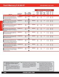
- Page 197 and 198: *This product is applicable only to
- Page 199 and 200: *This product is applicable only to
- Page 201 and 202: *This product is applicable only to
- Page 203 and 204: *This product is applicable only to
- Page 205 and 206: *This product is applicable only to
- Page 207 and 208: *This product is applicable only to
- Page 209 and 210: *This product is applicable only to
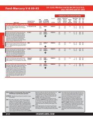
- Page 211 and 212: *This product is applicable only to
- Page 213 and 214: *This product is applicable only to
- Page 215 and 216: *This product is applicable only to
- Page 217 and 218: *This product is applicable only to
- Page 219 and 220: *This product is applicable only to
- Page 221 and 222: *This product is applicable only to
- Page 223 and 224: *This product is applicable only to
- Page 225 and 226: *This product is applicable only to
- Page 227 and 228: *This product is applicable only to
- Page 229 and 230: *This product is applicable only to
- Page 231 and 232: *This product is applicable only to
- Page 233 and 234: *This product is applicable only to
- Page 235 and 236: *This product is applicable only to
- Page 237 and 238: *This product is applicable only to
- Page 239 and 240:
*This product is applicable only to
- Page 241 and 242:
*This product is applicable only to
- Page 243 and 244:
nuts can be installed to permit ind
- Page 245 and 246:
*This product is applicable only to
- Page 247 and 248:
*This product is applicable only to
- Page 249 and 250:
*This product is applicable only to
- Page 251 and 252:
*This product is applicable only to
- Page 253 and 254:
*This product is applicable only to
- Page 255 and 256:
*This product is applicable only to
- Page 257 and 258:
*This product is applicable only to
- Page 259 and 260:
*This product is applicable only to
- Page 261 and 262:
*This product is applicable only to
- Page 263 and 264:
*This product is applicable only to
- Page 265 and 266:
*This product is applicable only to
- Page 267 and 268:
*This product is applicable only to
- Page 269 and 270:
*This product is applicable only to
- Page 271 and 272:
Oldsmobile DRCE V8 The DRCE (Drag R
- Page 273 and 274:
*This product is applicable only to
- Page 275 and 276:
*This product is applicable only to
- Page 277 and 278:
*This product is applicable only to
- Page 279 and 280:
*This product is applicable only to
- Page 281 and 282:
*This product is applicable only to
- Page 283 and 284:
*This product is applicable only to
- Page 285 and 286:
Cam and Valve Train Buyer’s Guide
- Page 287 and 288:
Camshaft Components Cam Degreeing B
- Page 289 and 290:
Distributor-Magneto Drive Gears Cop
- Page 291 and 292:
Distributor-Magneto Drive Gears Coa
- Page 293 and 294:
Lifters - Hydraulic and Mechanical
- Page 295 and 296:
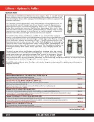
Lifters - Hydraulic Roller Hydrauli
- Page 297 and 298:
Lifters - Mechanical Roller Mechani
- Page 299 and 300:
Lifters - Mechanical Roller Pushrod
- Page 301 and 302:
Lifters - Mechanical Roller Applica
- Page 303 and 304:
Lifters - Mechanical Roller Applica
- Page 305 and 306:
Lubricants Assembly Lube (Paste) Cr
- Page 307 and 308:
Pushrods Overall Ends Application C
- Page 309 and 310:
Pushrods - One Piece Pro Series, On
- Page 311 and 312:
Pushrod Accessories Pushrod Guidepl
- Page 313 and 314:
Rocker Arms, Steel & Ductile Iron A
- Page 315 and 316:
Aluminum Rocker Arms, Energizer Ene
- Page 317 and 318:
Aluminum Roller Rockers, Gold Race
- Page 319 and 320:
Aluminum Roller Rockers, Gold Race
- Page 321 and 322:
Aluminum Shaft Mount Rocker Arms Ne
- Page 323 and 324:
Rocker Arm Adjusting Nuts, Screws R
- Page 325 and 326:
Rocker Arm Guideplate Conversion Ki
- Page 327 and 328:
Rocker Arm Studs Rocker Arm Studs C
- Page 329 and 330:
Timing Chains and Components Pro-Se
- Page 331 and 332:
Tools Pushrods, Adjustable Checking
- Page 333 and 334:
Vacuum Kits and Accessories Adjusta
- Page 335 and 336:
Valve Train Questions Valve Spring
- Page 337 and 338:
Valve Springs O.D I.D. Damper Seat
- Page 339 and 340:
Valve Springs O.D I.D.1 I.D.2 Dampe
- Page 341 and 342:
Valve Springs Valve Spring Spec Cha
- Page 343 and 344:
Valve Springs Valve Spring Spec Cha
- Page 345 and 346:
Valve Springs Valve Spring Spec Cha
- Page 347 and 348:
Valve Springs Valve Spring Spec Cha
- Page 349 and 350:
Valve Spring Retainers How to Use t
- Page 351 and 352:
Valve Spring Retainer Dimensions -
- Page 353 and 354:
Valve Spring Retainer Height Chart
- Page 355 and 356:
Valve Spring to Retainer Cross Refe
- Page 357 and 358:
Valve Spring to Retainer Cross Refe
- Page 359 and 360:
Valve Spring and Retainer Kits Valv
- Page 361 and 362:
Valve Stem Locks Multi-Fit Valve St
- Page 363 and 364:
Valve Train Stabilizers Durable ste
- Page 365 and 366:
How to Identify Your Crane Cam SERI
- Page 367 and 368:
Street/Strip, Off Road, Marine Cams
- Page 369 and 370:
Finish Grind Crane Round Lobe Outri
- Page 371 and 372:
Other Engine Applications Ford, Lin
- Page 373 and 374:
Flat Tappet Camshaft Break-in Proce
- Page 375 and 376:
Adjusting the Valve Train Hydraulic
- Page 377 and 378:
Commonly Asked Valve Spring Questio
- Page 379 and 380:
Cam and Valve Train Questions Commo
- Page 381 and 382:
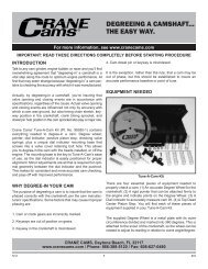
Degreeing the Cam Degreeing the Cam
- Page 383 and 384:
Degreeing the Cam Degreeing the Cam
- Page 385 and 386:
Understanding the Cam Specification
- Page 387 and 388:
Ignition Table of Contents HI-6S Mu
- Page 389 and 390:
Street Performance, Trucks, Trailer
- Page 391 and 392:
Street, Street Performance, Race HI
- Page 393 and 394:
Street Performance, Race HI-6R/Digi
- Page 395 and 396:
Street Performance, Race, Turbo HI-
- Page 397 and 398:
Street Performance, Race, Turbo HI-
- Page 399 and 400:
Oval Track, Race HI-6N CD Ignition
- Page 401 and 402:
Timing Retard Timing Retard Control
- Page 403 and 404:
Points Conversion Ignition XR-i Poi
- Page 405 and 406:
Points Conversion Ignition XR700 Re
- Page 407 and 408:
Points Conversion Ignition XR3000 R
- Page 409 and 410:
Distributors Race Billet Distributo
- Page 411 and 412:
Distributors Oval Track Pro Race Di
- Page 413 and 414:
Performance Ignition Coils LX91, LX
- Page 415 and 416:
Performance Ignition Coils PS91, PS
- Page 417 and 418:
Performance Plug Wires 8.5mm Fire W
- Page 419 and 420:
FireWire Spark Plug Wire Now Availa
- Page 421 and 422:
Part Number Index Part No. Page No.
- Page 423 and 424:
Part Number Index Part No. Page No.
- Page 425 and 426:
Part Number Index Part No. Page No.
- Page 427 and 428:
Part Number Index Part No. Page No.
- Page 429 and 430:
Part Number Index Part No. Page No.
- Page 431 and 432:
Part Number Index Part No. Page No.
- Page 433 and 434:
Part Number Index Part No. Page No.