2011 - Crane Cams
2011 - Crane Cams
2011 - Crane Cams

You also want an ePaper? Increase the reach of your titles
YUMPU automatically turns print PDFs into web optimized ePapers that Google loves.
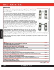
VALVE TRAIN<br />
Cam Timing Explained<br />
Cam Timing Explained<br />
Cam advance, lobe separation, lobe centerline, intake<br />
lobe centerline, etc. are all terms being used for comparing<br />
and devising camshaft specifications. With so<br />
many similar terms being used, there can be a bit of<br />
confusion when folks from different backgrounds start<br />
talking about them.<br />
Lobe separation is the measurement in CAM degrees<br />
between the maximum lift point of the exhaust lobe to<br />
the maximum lift point of the intake lobe on any cylinder.<br />
Some also refer to this as lobe centerline. This<br />
dimension is ground into the camshaft and can not be<br />
changed by advancing or retarding the camshaft<br />
(unless it’s an engine with separate intake and exhaust<br />
cams.)<br />
Intake lobe centerline, or intake maximum lift, refers to<br />
the distance in crankshaft degrees from the cylinder’s<br />
Top Dead Center point to the maximum lift point of the<br />
intake lobe on any one cylinder. This is usually measured<br />
as degrees After Top Dead Center. This figure<br />
WILL change when the cam is advanced or retarded. As<br />
you advance the cam, this number will get smaller, as<br />
you are opening it fewer degrees AFTER Top Dead<br />
Center. Retarding the cam will make this number larger,<br />
as you are opening it more degrees AFTER Top Dead<br />
Center.<br />
Exhaust lobe centerline, or exhaust maximum lift, is<br />
usually expressed in crankshaft degrees Before Top<br />
Dead Center. As you advance the cam, this number will<br />
get larger, since you are opening it more degrees<br />
BEFORE Top Dead Center. Retarding the cam will make<br />
this number smaller.<br />
The average of the intake lobe centerline and the<br />
exhaust lobe centerline should equal your lobe separation.<br />
The cam timing figures (as measured at a specific lobe<br />
lift: .004”, .020”, .050”, etc.) may show the maximum lift<br />
point to be distorted when you’re dealing with nonsymmetrical<br />
camshaft lobes (the opening side has a different<br />
shape than the closing side). If you split the difference<br />
between the opening and closing figures at<br />
.020” or .050” lobe lift, this figure will not coincide with<br />
the actual maximum lift point of the lobe. There are<br />
instances where a non-symmetrical intake lobe is paired<br />
with a symmetrical exhaust lobe (or vice-versa), or lobes<br />
with varying amounts of non-symmetry may be used as<br />
intake and exhaust. We believe that where the opening<br />
and closing events actually occur are the most important<br />
figures to pay attention to when degreeing your<br />
camshaft. Just finding the maximum lift points doesn’t<br />
really tell you anything about the camshaft, or it’s even<br />
the correct camshaft! By documenting the opening<br />
and closing numbers as you tune, you will gain more<br />
knowledge as to what actually helps or hinders your<br />
performance. This is also a good time to emphasize<br />
keeping track of your cranking compression whenever<br />
you change valve lash, cam timing, rocker arm ratio,<br />
and especially when changing camshafts.<br />
384<br />
CRANECAMS.COM<br />
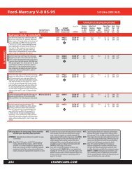
You may have noticed that most <strong>Crane</strong> <strong>Cams</strong> have a<br />
certain amount of advance ground into them when you<br />
check out the cam specification card. This is primarily<br />
done to insure that you have adequate torque to establish<br />
a good performance baseline. We have also found<br />
over the years, that the correct camshaft for most applications<br />
will run best with some amount of advance in it.<br />
We believe that it’s certainly better to begin with too<br />
much bottom end and mid-range torque, and tune<br />
from there, than to have a shortage of torque, and try<br />
to figure out how to compensate for that.<br />
The following is a general rule for how we grind most of<br />
our camshafts:<br />
Lobe Separation Degrees Advance<br />
Up to 102 0<br />
103-104 2<br />
105 3<br />
106-107 4<br />
108 or more 5<br />
This has certainly not been a list of all of the terms and<br />
philosophies we use when producing our camshafts,<br />
but it will hopefully provide a bit of insight as to some<br />
of our methods of camshaft recommendation and production.<br />
We invite any questions or comments that you<br />
may have.