2011 - Crane Cams
2011 - Crane Cams
2011 - Crane Cams

You also want an ePaper? Increase the reach of your titles
YUMPU automatically turns print PDFs into web optimized ePapers that Google loves.
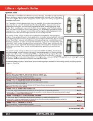
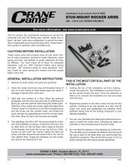
Adjusting the Valve Train<br />
Hydraulic Lifters (continued)<br />
increase preload, a shorter to reduce preload. <strong>Crane</strong> offers<br />
various length pushrods, (see pages 306 through 309) and<br />
offers custom length pushrods (see page 305).<br />
Many methods are illustrated throughout the catalog, here<br />
are a few of them:<br />
• Custom length pushrods<br />
• Bottleneck stud shims<br />
• Bridge mount rocker arm shims<br />
• Pedestal mount rocker arm shims<br />
• Adjustable conversion rocker arm studs/kits<br />
• “Kool Nut” adjusting nuts<br />
• Guideplate and rocker arm conversion kits<br />
• Adjustable rocker arms (both stud and shaft mounted)<br />
• Replacement guideplates and studs<br />
Using Adjustable Rocker Arms to set Hydraulic Lifter<br />
Preload<br />
The easiest method to arrive at proper lifter preload is when<br />
you have an engine with “Adjustable Valve Train”. Unfortunately,<br />
since 1967 most domestic engines, with the exception of small<br />
and big block Chevrolets, have been made with non-adjustable<br />
rocker arms. The <strong>Crane</strong> Catalog shows you several ways of<br />
converting your engine to an adjustable rocker arm system.<br />
The following sections will describe how to set the preload<br />
with adjustable rocker arms.<br />
Hydraulic Lifters Can Be Adjusted at Any Engine<br />
Temperature<br />
Since hydraulic lifters can compensate for thermal expansion<br />
of the engine, the adjusting can be done with the<br />
engine cold; hot adjustment is not necessary.<br />
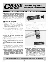
Adjusting Hydraulic Lifters for Proper Preload<br />
In order to adjust the preload, the lifter must be properly<br />
located on the base circle or “Heel” of the lobe.<br />
(See Figure 2.) At this position the valve is closed and there<br />
is no lift taking place. You will need to watch the movement<br />
of the valves to determine which lifter is properly positioned<br />
for adjusting.<br />
1. Remove the valve covers, and pick a cylinder that you are<br />
going to set the preload on.<br />
2. Hand rotate the engine in its normal direction of rotation<br />
and watch the exhaust valve on that particular cylinder.<br />
When the exhaust valve begins to open, stop and adjust<br />
that cylinder’s intake rocker arm. (Why? Because when the<br />
exhaust valve is just beginning to open, the intake lifter<br />
will be on the base circle of the lobe, the correct position<br />
for adjusting the intake.)<br />
3. Back off the intake rocker arm adjuster and remove any<br />
tension from the pushrod. Wait a minute or two for that<br />
hydraulic lifter to return to a neutral position. The spring<br />
inside the lifter will move the pushrod seat up against the<br />
retaining lock if you give it time to do so. (If you are<br />
installing brand new lifters they will be in the neutral<br />
position when they come in the box.)<br />
4. Now spin the intake pushrod with your fingers while<br />
tightening down the rocker arm. When you feel a slight<br />
resistance to the turning of the pushrod, you are at “Zero<br />
Lash”. Turn the adjusting nut down one half to one full<br />
turn from that point. Lock the adjuster into position. The<br />
intake is now adjusted properly.<br />
5. Continue to hand turn the engine, watching that same<br />
intake. It will go to full open and then begin to close.<br />
When it is almost closed, stop and adjust the exhaust<br />
rocker arm on that particular cylinder. (Again, when we<br />
see the intake almost closed, we are sure that exhaust lifter<br />
is on the base circle of the lobe.) Loosen the exhaust<br />
rocker arm and follow the same procedure described<br />
before in steps 3 and 4 to adjust this rocker arm.<br />
6. Both valves on this cylinder are now adjusted, and you<br />
can move on to your next cylinder and follow the same<br />
procedure again.<br />
Do Hydraulic Lifters Need to be Primed with Oil?<br />
Many people mistakenly believe that hydraulic lifters must<br />
be soaked in oil overnight and be hand pumped up with a<br />
pushrod before installing into a new engine, however this is<br />
not necessary. In fact, this could cause the lifter to act as a<br />
“solid” and prevent obtaining proper preload.<br />
What is very necessary is the priming of the entire engine’s<br />
oil system before starting up a new engine for the first time.<br />
This is done by turning the oil pump with a drill motor to<br />
force oil throughout the entire engine. <strong>Crane</strong> <strong>Cams</strong> offers oil<br />
pump primers for Chevrolet and Ford engines. (see page<br />
331)<br />
What is a Hi Intensity Hydraulic Lifter?<br />
Part of engineering a hydraulic lifter is to determine what its<br />
“Bleed Rate” will be. The “Bleed Rate” is a scientific method<br />
of determining the time it takes the hydraulic lifter to lose<br />
its pressure once it is fully pumped up solid with oil. By<br />
changing this rate, the lifter can give different performance<br />
factors to the engine. One such design is the <strong>Crane</strong> <strong>Cams</strong> Hi<br />
Intensity Lifter. Its increased bleed rate enables it to provide<br />
improved vacuum, increased cylinder pressure and performance<br />
in the lower RPM ranges. It is best suited for those<br />
engines that are using a big camshaft profile that requires<br />
more compression ratio than the engine actually has. This<br />
situation would normally cause a loss of bottom end performance,<br />
but with the <strong>Crane</strong> <strong>Cams</strong> Hi Intensity Lifter the bottom<br />
end torque is restored.<br />
NOTE: Hi Intensity Lifters are only for use if the compression<br />
ratio is below the recommended minimum shown<br />
on the application page for the particular camshaft you<br />
have selected. Otherwise higher than desired cylinder<br />
pressures may result, causing detonation.<br />
Correct Position<br />
of the Cam Lobe and Lifter<br />
for setting preload.<br />
Incorrect Positions<br />
Figure 2<br />
866-388-5120 • 386-236-9983 FAX 375