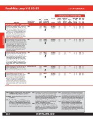
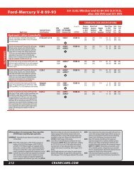
2011 - Crane Cams
2011 - Crane Cams
2011 - Crane Cams

Create successful ePaper yourself
Turn your PDF publications into a flip-book with our unique Google optimized e-Paper software.
VALVE TRAIN<br />
Adjusting the Valve Train<br />
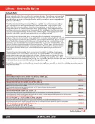
Hydraulic Lifters<br />
Hydraulic lifters have been the choice of the automotive<br />
industry for many years for several good reasons. When<br />
compared to a mechanical lifter, the hydraulics are:<br />
1. Quieter.<br />
2. Low maintenance.<br />
3. Able to adjust for thermal expansion of the engine.<br />
4. Considered as a built in shock absorber, eases stress on<br />
valve train.<br />
5. Capable of having a “Bleed Rate” that can be designed to<br />
accommodate different engine RPM ranges.<br />
Most engines use either the standard design hydraulic lifter<br />
or the low friction, high performance hydraulic roller design.<br />
Hydraulic lifters are the best for street applications, high<br />
performance, and mild racing applications where low maintenance<br />
and low cost is a primary concern.<br />
What is the difference in the design of a Hydraulic and<br />
Mechanical Lifter?<br />
Basically, the hydraulic lifter pushrod seat is moveable, the<br />
mechanical lifter seat is not. Both lifter types can look the<br />
same from the outside, with both usually having pushrod<br />
seats held in by a retaining lock. The pushrod seat in a<br />
mechanical lifter usually registers upon an internal step<br />
inside the lifter body preventing it from moving (thus it gets<br />
the nickname “Solid Lifter”). What’s below the pushrod seat<br />
in the hydraulic lifter is a different story. Its pushrod seat is<br />
not restricted by a step, but instead sits on top of a moveable<br />
hydraulic mechanism which acts like a tiny hydraulic<br />
pump. Below this mechanism is valving, and a spring to produce<br />
an upward force, moving the pushrod seat upward<br />
against the retaining lock.<br />
What is Hydraulic Lifter Preload?<br />
Mechanical cam designs require a running clearance or<br />
valve lash, while hydraulic lifters are just the opposite. When<br />
the rocker arm assembly is properly torqued down into<br />
position, the pushrod must take up all the clearance and<br />
descend into the hydraulic lifter, causing the pushrod seat<br />
to move down by .020” to .060”. The distance that the pushrod<br />
seat moves down away from the retaining lock is the<br />
“Lifter Preload”. The hydraulic mechanism requires this precise<br />
amount of “preload” for it to do its job properly.<br />
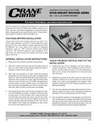
(See Figure 1.)<br />
What happens if the amount of Hydraulic Lifter Preload is<br />
wrong?<br />
If clearance exists between the pushrod and the seat in the<br />
hydraulic lifter, after the rocker arm assembly has been<br />
torqued down, you will have no lifter preload. In this case<br />
the valve train will be noisy when the engine is running. All<br />
of the hydraulic force produced by the lifter will be exerted<br />
374<br />
Hydraulic in<br />
Neutral Position<br />
Pushrod<br />
Retaining<br />
Lock<br />
Pushrod<br />
Seat<br />
Hydraulic Lifter<br />
with Proper Preload<br />
Figure 1<br />
CRANECAMS.COM<br />
against the lifter’s retaining lock, and this could cause the<br />
lock to fail.<br />
If the opposite occurs, and the pushrod descends too far<br />
(more than .060”) with the lifter on the base circle, then you<br />
may have excessive lifter preload. In theory, a hydraulic lifter<br />
will only pump up to whatever preload it is set to. With<br />
excessive preload, as the engine RPM and oil pressure<br />
increases, the hydraulic mechanism could pump-up the<br />
pushrod seat if the valve spring cannot control the proper<br />
motion of the valve. This could cause the valve to stay off its<br />
seat during most of, or all, its entire cycle. This reduces the<br />
cylinder pressure, lowering the performance of the engine.<br />
Backfiring may also occur. The following sections will offer<br />
suggestions on how to correct this.<br />
When rebuilding an engine, what can cause Lifter Preload<br />
to change?<br />
Almost anything can affect lifter preload. If you do a valve<br />
job, surface the block or heads, change the head gasket<br />
thickness, or buy a new camshaft, the amount of preload<br />
can be affected. Sometimes these changes cancel one<br />
another out and your preload stays the same; this is more<br />
by luck than design. This is why you must always inspect the<br />
amount of preload the lifter has when reassembling the<br />
engine and be sure that it is correct.<br />
A Fast and Easy Way to Check Hydraulic Lifter Preload<br />
when using Non-Adjustable Rocker Arms<br />
With the cam, hydraulic lifters and pushrods in place, install<br />
your rocker arm assembly. Use the prescribed method in<br />
your repair manual and torque down all the valve train bolts<br />
in the proper sequence. Pick a cylinder that you are going to<br />
check. Hand rotate the engine in its normal direction of<br />
rotation until both valves are closed. You are on the compression<br />
cycle for that cylinder. (At this position the valve<br />
springs are at their least amount of tension making the job<br />
a little easier to do.) Wait a few minutes, allowing the lifters<br />
to bleed down. Now, lay a rigid straightedge across the cylinder<br />
head, supporting it on the surface of the head where<br />
the valve cover gasket would go. Using a metal scribe and<br />
the straightedge, carefully scribe a line on both pushrods.<br />
Now carefully remove the torque from all valve train bolts,<br />
removing any pressure from the pushrods. Wait a few minutes<br />
for the pushrod seat in the hydraulic lifter to move back<br />
to the neutral position. Carefully scribe a new line on both<br />
pushrods. Measure the distance between the two scribe<br />
marks, it represents the amount of lifter preload. If the lines<br />
are .020” to .060” apart you have proper lifter preload. If the<br />
lines are the same or less than .020” apart you have no, or<br />
insufficient, preload. If the lines are further apart than .060”,<br />
you have excessive lifter preload. To bring your preload into<br />
tolerance, use one of the methods described in the next<br />
section if necessary, or call the <strong>Crane</strong> Tech Line for assistance<br />
(866-388-5120).<br />
Methods to Adjust for Proper Hydraulic Lifter Preload<br />
There are several different methods for increasing or<br />
decreasing the amount of lifter preload, depending on valve<br />
train design and how the rocker arm is held onto the cylinder<br />
head. Keep in mind that the automotive manufacturers<br />
have made changes to the valve train over the years. What<br />
may work on one year’s engine may not work for another,<br />
even though they are basically the same engine. There is<br />
one method that universally works on all these engines,<br />
change the pushrod length! Use a longer pushrod to