

SonTek/YSI Argonaut-XR Technical Manual - HydroScientific West
SonTek/YSI Argonaut-XR Technical Manual - HydroScientific West
SonTek/YSI Argonaut-XR Technical Manual - HydroScientific West

Create successful ePaper yourself
Turn your PDF publications into a flip-book with our unique Google optimized e-Paper software.
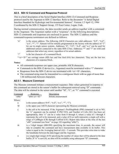
A2.5. SDI-12 Command and Response Protocol<br />
<strong>Argonaut</strong> Operation <strong>Manual</strong> Firmware Version 7.9 (May 1, 2001)<br />
<strong>SonTek</strong>/<strong>YSI</strong><br />
This is a brief description of the Serial Digital Interface (SDI-12) Command and Response<br />
protocol used by the <strong>Argonaut</strong> to SDI-12 interface. Refer to the document “A Serial Digital<br />
Interface Standard for Hydrologic and Environmental Sensors”. Version 1.2 April 12, 1996<br />
Coordinated by the SDI-12 Support Group, 135 East Center, Logan, Utah.<br />
During normal communication, the data recorder sends an address together with a command<br />
to the <strong>Argonaut</strong>. The <strong>Argonaut</strong> replies with a “response”. In the following descriptions,<br />
SDI-12 commands and responses are enclosed in quotes. The SDI-12 address and the<br />
command/response terminators are defined as follows:<br />
“a” is the sensor address. The following ASCII Characters are valid addresses: “0-9”, “A-Z”,<br />
“a-z”, “*”, “?”. Sensors will be initially programmed at the factory with the address of “1”<br />
for use in single sensor systems. Addresses “0”, “2-9”, “A-Z”, and “a-z” can be used for<br />
additional sensors connected to the same SDI-12 bus. Addresses “*” and “?” are wild card<br />
addresses that select any sensor, regardless of its actual address.<br />
“!” is the last character of a command block.<br />
“” are carriage return (0D) hex and line feed (0A) hex characters. They are the last two<br />
characters of a response block.<br />
Notes:<br />
• All commands/responses are upper case, printable ASCII characters.<br />
• Commands to the SDI-12 device (i.e., <strong>Argonaut</strong>) must be terminated with a “!” character.<br />
• Responses from the SDI-12 device are terminated with characters.<br />
• The command string must be transmitted in a contiguous block with no gaps of more than<br />
1.66 milliseconds between characters.<br />
A2.5.1. Measure Command<br />
The Measure command initiates a measurement sequence. Data values generated in response to<br />
this command are stored in the sensor’s buffer for subsequent retrieval using “D” commands.<br />
The data will be retained in the sensor until another “M”, “C”, or “V” command is executed.<br />
Command Response Description<br />
“aMc!”<br />
Where:<br />
“atttn” Initiate measurement<br />
a is the sensor address (“0-9”, “A-Z”, “a-z”, “*”, “?”).<br />
M is the upper case ASCII character representing the Measure command.<br />
c is the cell to be measured. If the <strong>Argonaut</strong>’s ProfilingMode (PM) command is set to NO,<br />
the “c” argument can be omitted. If PM=YES, and Number of Cells (NC) has been set<br />
appropriately, then “c” can be a value from 0 through 5, where a value of 1 through 5<br />
represents the cell to be measured, and a value of 0 (or null) represents a single cell with a<br />
range of CellBegin (CB) through CellEnd (CE). Report data taken at the time of the last<br />
“aM!” command (see Note †† on page 102 regarding “aMn!”).<br />
ttt is a 3-digit integer (000-999) specifying the maximum time, in seconds, the sensor will<br />
take to complete the command and have measurement data available in its buffer. This<br />
value is equal to the Averaging Interval (AI) + 5 seconds. This provides extra time to wake<br />
the handshake between the data-logger and the <strong>Argonaut</strong>.<br />
n is a single-digit integer (0-9) specifying the number of values that will be placed in the data<br />
buffer. If “n” is zero (0), no data will be available using subsequent “D” commands.<br />
103