Denon AVR-3313 Manual - Audio Products Australia
Denon AVR-3313 Manual - Audio Products Australia
Denon AVR-3313 Manual - Audio Products Australia

Create successful ePaper yourself
Turn your PDF publications into a flip-book with our unique Google optimized e-Paper software.
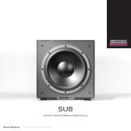
Connecting an HDMI-incompatible device<br />
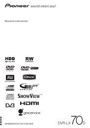
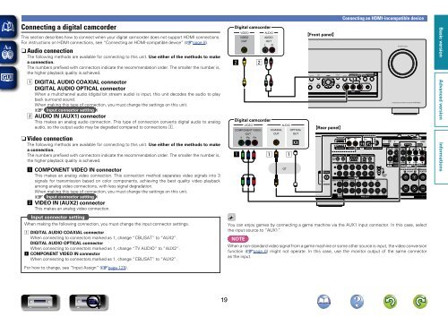
Connecting a digital camcorder<br />
Digital camcorder<br />
This section describes how to connect when your digital camcorder does not support HDMI connections.<br />
For instructions on HDMI connections, see “Connecting an HDMI-compatible device” (vpage 8).<br />
nn<strong>Audio</strong> connection<br />
The following methods are available for connecting to this unit. Use either of the methods to make<br />
a connection.<br />
The numbers prefixed with connectors indicate the recommendation order. The smaller the number is,<br />
the higher playback quality is achieved.<br />
s<br />
VIDEO<br />
VIDEO<br />
OUT<br />
s<br />
AUDIO<br />
AUDIO<br />
OUT<br />
L R<br />
L<br />
R<br />
GFront panelH<br />
a DIGITAL AUDIO COAXIAL connector<br />
DIGITAL AUDIO OPTICAL connector<br />
When a multichannel audio (digital bit stream audio) is input, this unit decodes the audio to play<br />
back surround sound.<br />
When making this type of connection, you must change the settings on this unit.<br />
(v Input connector setting )<br />
s AUDIO IN (AUX1) connector<br />
This makes an analog audio connection. This type of connection converts digital audio to analog<br />
audio, so the output audio may be degraded compared to connections a.<br />
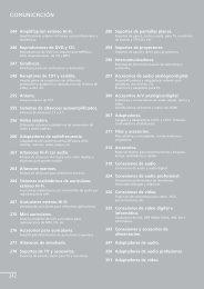
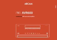
nnVideo connection<br />
The following methods are available for connecting to this unit. Use either of the methods to make<br />
a connection.<br />
The numbers prefixed with connectors indicate the recommendation order. The smaller the number is,<br />
the higher playback quality is achieved.<br />
Digital camcorder<br />
VIDEO<br />
COMPONENT VIDEO<br />
OUT<br />
Y PB PR<br />
a<br />
L<br />
R<br />
a<br />
COAXIAL<br />
OUT<br />
AUDIO<br />
a<br />
OPTICAL<br />
OUT<br />
GRear panelH<br />
a COMPONENT VIDEO IN connector<br />
This makes an analog video connection. This connection method separates video signals into 3<br />
signals for transmission based on color components, achieving the best quality video playback<br />
among analog video connections, with less signal degradation.<br />
When making this type of connection, you must change the settings on this unit.<br />
(v Input connector setting )<br />
s VIDEO IN (AUX2) connector<br />
This makes an analog video connection.<br />
or<br />
Input connector setting<br />
When making the following connection, you must change the input connector settings.<br />
a DIGITAL AUDIO COAXIAL connector<br />
When connecting to connectors marked as 1, change “CBL/SAT” to “AUX2”.<br />
DIGITAL AUDIO OPTICAL connector<br />
When connecting to connectors marked as 1, change “TV AUDIO” to “AUX2”.<br />
a COMPONENT VIDEO IN connector<br />
When connecting to connectors marked as 1, change “CBL/SAT” to “AUX2”.<br />
You can enjoy games by connecting a game machine via the AUX1 input connector. In this case, select<br />
the input source to “AUX1”.<br />
NOTE<br />
When a non-standard video signal from a game machine or some other source is input, the video conversion<br />
function (vpage 6) might not operate. In this case, use the monitor output of the same connector<br />
as the input.<br />
For how to change, see “Input Assign” (vpage 125).<br />
19