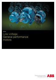
Manual - Famco
Manual - Famco
Manual - Famco
- No tags were found...

Create successful ePaper yourself
Turn your PDF publications into a flip-book with our unique Google optimized e-Paper software.
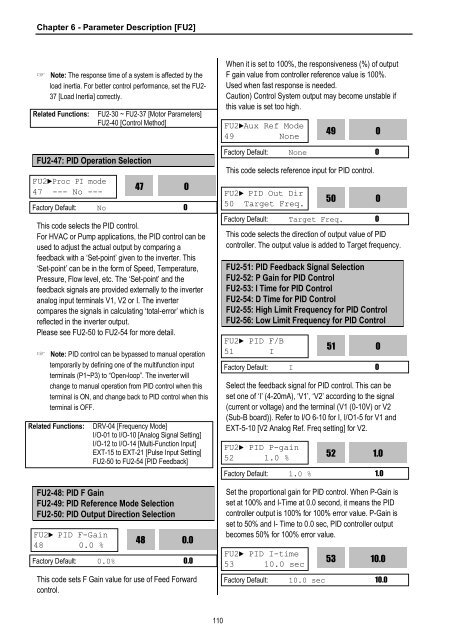
Chapter 6 - Parameter Description [FU2]☞ Note: The response time of a system is affected by theload inertia. For better control performance, set the FU2-37 [Load Inertia] correctly.Related Functions:FU2-47: PID Operation SelectionFU2►Proc PI mode47 --- No ---FU2-30 ~ FU2-37 [Motor Parameters]FU2-40 [Control Method]This code selects the PID control.For HVAC or Pump applications, the PID control can beused to adjust the actual output by comparing afeedback with a ‘Set-point’ given to the inverter. This‘Set-point’ can be in the form of Speed, Temperature,Pressure, Flow level, etc. The ‘Set-point’ and thefeedback signals are provided externally to the inverteranalog input terminals V1, V2 or I. The invertercompares the signals in calculating ‘total-error’ which isreflected in the inverter output.Please see FU2-50 to FU2-54 for more detail.☞ Note: PID control can be bypassed to manual operationtemporarily by defining one of the multifunction inputterminals (P1~P3) to “Open-loop”. The inverter willchange to manual operation from PID control when thisterminal is ON, and change back to PID control when thisterminal is OFF.47Factory Default: No 0Related Functions:FU2-48: PID F GainFU2-49: PID Reference Mode SelectionFU2-50: PID Output Direction SelectionFU2► PID F-Gain48 0.0 %DRV-04 [Frequency Mode]I/O-01 to I/O-10 [Analog Signal Setting]I/O-12 to I/O-14 [Multi-Function Input]EXT-15 to EXT-21 [Pulse Input Setting]FU2-50 to FU2-54 [PID Feedback]48This code sets F Gain value for use of Feed Forwardcontrol.00.0Factory Default: 0.0% 0.0When it is set to 100%, the responsiveness (%) of outputF gain value from controller reference value is 100%.Used when fast response is needed.Caution) Control System output may become unstable ifthis value is set too high.FU2►Aux Ref Mode49 NoneThis code selects reference input for PID control.This code selects the direction of output value of PIDcontroller. The output value is added to Target frequency.FU2-51: PID Feedback Signal SelectionFU2-52: P Gain for PID ControlFU2-53: I Time for PID ControlFU2-54: D Time for PID ControlFU2-55: High Limit Frequency for PID ControlFU2-56: Low Limit Frequency for PID ControlFU2► PID F/B51 ISelect the feedback signal for PID control. This can beset one of ‘I’ (4-20mA), ‘V1’, ‘V2’ according to the signal(current or voltage) and the terminal (V1 (0-10V) or V2(Sub-B board)). Refer to I/O 6-10 for I, I/O1-5 for V1 andEXT-5-10 [V2 Analog Ref. Freq setting] for V2.Set the proportional gain for PID control. When P-Gain isset at 100% and I-Time at 0.0 second, it means the PIDcontroller output is 100% for 100% error value. P-Gain isset to 50% and I- Time to 0.0 sec, PID controller outputbecomes 50% for 100% error value.51Factory Default: I 0FU2► PID P-gain52 1.0 % 521.0Factory Default: 1.0 % 1.0FU2► PID I-time53 10.0 sec49Factory Default: None 0FU2► PID Out Dir50 Target Freq.50Factory Default: Target Freq. 053010.0Factory Default: 10.0 sec 10.000110