- Page 3: CAUTION• Install the inverter on
- Page 6: (9) UL Marking1. Short Circuit Rati
- Page 9 and 10: USER SELECTION GUIDE (iS5 SPECIFICA
- Page 11 and 12: CONTROLOPERATIONProtectionDisplayEn
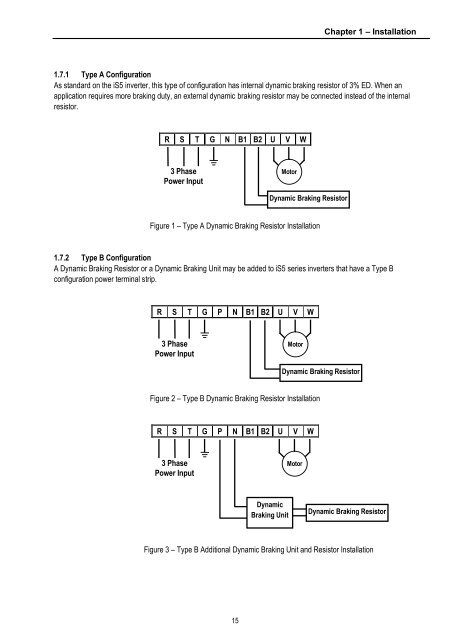
- Page 13 and 14: Chapter 1 - Installation1.4 Other P
- Page 15 and 16: Chapter 1 - Installation• Frame #
- Page 17 and 18: Chapter 1 - Installation• Frame #
- Page 19: Chapter 1 - Installation1.6 Basic W
- Page 23 and 24: Chapter 1 - InstallationWARNINGNorm
- Page 25 and 26: Chapter 1 - Installation1.8 Control
- Page 28 and 29: Chapter 1 - InstallationNotes:22
- Page 31 and 32: Chapter 2 - Operation2.2.1 LCD Keyp
- Page 33 and 34: Chapter 2 - Operation2.2.3 Paramete
- Page 35 and 36: Chapter 2 - Operation2.3.1 7-Segmen
- Page 37 and 38: Chapter 2 - Operation2.3.3 Paramete
- Page 39 and 40: Chapter 2 - Operation2.5 Operating
- Page 41 and 42: Chapter 2 - Operation2.5.2 Operatio
- Page 43 and 44: Chapter 2 - Operation2.5.3 Operatio
- Page 45 and 46: Chapter 3 - Function Settings3) V/F
- Page 47 and 48: Chapter 3 - Function SettingsParame
- Page 49 and 50: Chapter 3 - Function Settings5) Par
- Page 51 and 52: Chapter 3 - Function Settings3) Aut
- Page 53 and 54: MODE PROG ENTREVSTOPRESETSHIFTESCFW
- Page 55 and 56: Chapter 3 - Function SettingsOperat
- Page 57 and 58: CHAPTER 4 -QUICK-START PROCEDURESTh
- Page 59 and 60: Chapter 4 - Quick start procedures4
- Page 61 and 62: Chapter 4 - Quick start procedures4
- Page 63 and 64: Chapter 5 - Parameter ListCodeDescr
- Page 65 and 66: Chapter 5 - Parameter ListCodeFU1-2
- Page 67 and 68: Chapter 5 - Parameter ListCodeDescr
- Page 69 and 70: Chapter 5 - Parameter ListCodeFU2-7
- Page 71 and 72:
Chapter 5 - Parameter ListCodeI/O-1
- Page 73 and 74:
Chapter 5 - Parameter ListCodeI/O-4
- Page 75 and 76:
Chapter 5 - Parameter ListCodeI/O-9
- Page 77 and 78:
Chapter 5 - Parameter ListCodeEXT-0
- Page 79 and 80:
Chapter 5 - Parameter ListCodeEXT-3
- Page 81 and 82:
Chapter 5 - Parameter ListCodeDescr
- Page 83 and 84:
Chapter 5 - Parameter List5.8 Sub-B
- Page 85 and 86:
CHAPTER 6 -PARAMETER DESCRIPTION6.1
- Page 87 and 88:
Chapter 6 - Parameter Description [
- Page 89 and 90:
Chapter 6 - Parameter Description [
- Page 91 and 92:
Chapter 6 - Parameter Description [
- Page 93 and 94:
Chapter 6 - Parameter Description [
- Page 95 and 96:
Chapter 6 - Parameter Description [
- Page 97 and 98:
Chapter 6 - Parameter Description [
- Page 99 and 100:
Chapter 6 - Parameter Description [
- Page 101 and 102:
Chapter 6 - Parameter Description [
- Page 103 and 104:
Chapter 6 - Parameter Description [
- Page 105 and 106:
Chapter 6 - Parameter Description [
- Page 107 and 108:
Chapter 6 - Parameter Description [
- Page 109 and 110:
Chapter 6 - Parameter Description [
- Page 111 and 112:
Chapter 6 - Parameter Description [
- Page 113 and 114:
Chapter 6 - Parameter Description [
- Page 115 and 116:
Chapter 6 - Parameter Description [
- Page 117 and 118:
Chapter 6 - Parameter Description [
- Page 119 and 120:
Chapter 6 - Parameter Description [
- Page 121 and 122:
Chapter 6 - Parameter Description [
- Page 123 and 124:
Chapter 6 - Parameter Description [
- Page 125 and 126:
Chapter 6 - Parameter Description [
- Page 127 and 128:
Chapter 6 - Parameter Description [
- Page 129 and 130:
Chapter 6 - Parameter Description [
- Page 131 and 132:
Chapter 6 - Parameter Description [
- Page 133 and 134:
Chapter 6 - Parameter Description [
- Page 135 and 136:
Chapter 6 - Parameter Description [
- Page 137 and 138:
Chapter 6 - Parameter Description [
- Page 139 and 140:
Chapter 6 - Parameter Description [
- Page 141 and 142:
Chapter 6 - Parameter Description [
- Page 143 and 144:
Chapter 6 - Parameter Description [
- Page 145 and 146:
Chapter 6 - Parameter Description [
- Page 147 and 148:
Chapter 6 - Parameter Description [
- Page 149 and 150:
Chapter 6 - Parameter Description [
- Page 151 and 152:
Chapter 6 - Parameter Description [
- Page 153 and 154:
Chapter 6 - Parameter Description [
- Page 155 and 156:
Chapter 6 - Parameter Description [
- Page 157 and 158:
Chapter 6 - Parameter Description [
- Page 159 and 160:
CHAPTER 7 -OPTIONSThe iS5 series in
- Page 161 and 162:
Chapter 7 - Options7.1 Sub-A board7
- Page 163 and 164:
Chapter 7 - Options7.2 Sub-B Board7
- Page 165 and 166:
Chapter 7 - Options1. Sub-B board w
- Page 167 and 168:
Chapter 7 - Options7.3 Sub-C Board
- Page 169 and 170:
Chapter 7 - Options7.4 Communicatio
- Page 171 and 172:
Chapter 7 - Options7.5 KeypadThe iS
- Page 174 and 175:
Chapter 7 - Options2) DB Resistor (
- Page 176 and 177:
Chapter 7 - Options· DB resistor w
- Page 178 and 179:
Chapter 7 - Options· DB Resistor/U
- Page 180 and 181:
Chapter 7 - Options* Type 2 (Max. 6
- Page 182 and 183:
Chapter 7 - Options3) DB Resistor/U
- Page 184 and 185:
Chapter 7 - Options• Group 2802-
- Page 186 and 187:
Chapter 7 - Options(5) Monitoring L
- Page 188 and 189:
Chapter 8 - Troubleshooting & Maint
- Page 190 and 191:
Chapter 8 - Troubleshooting & Maint
- Page 192 and 193:
Chapter 8 - Troubleshooting & Maint
- Page 194 and 195:
Chapter 8 - Troubleshooting & Maint
- Page 196 and 197:
APPENDIX B - PARAMETERS BASED ON AP
- Page 198 and 199:
APPENDIX C- PERIPHERAL DEVICESInver
- Page 200 and 201:
DECLARATION OF CONFORMITYCouncil Di
- Page 202 and 203:
EMI / RFI POWER LINE FILTERSRFI FIL
- Page 204 and 205:
EMI / RFI POWER LINE FILTERSRFI Fil