Manual - Famco
Manual - Famco
Manual - Famco
- No tags were found...

Create successful ePaper yourself
Turn your PDF publications into a flip-book with our unique Google optimized e-Paper software.
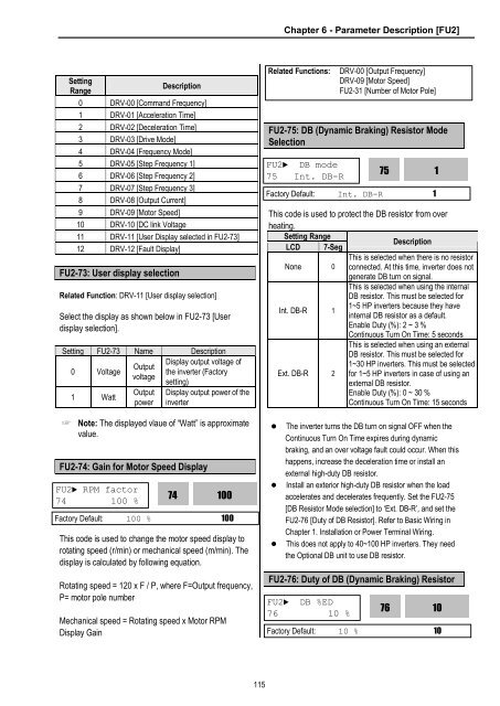
Chapter 6 - Parameter Description [FU2]SettingRangeDescription0 DRV-00 [Command Frequency]1 DRV-01 [Acceleration Time]2 DRV-02 [Deceleration Time]3 DRV-03 [Drive Mode]4 DRV-04 [Frequency Mode]5 DRV-05 [Step Frequency 1]6 DRV-06 [Step Frequency 2]7 DRV-07 [Step Frequency 3]8 DRV-08 [Output Current]9 DRV-09 [Motor Speed]10 DRV-10 [DC link Voltage11 DRV-11 [User Display selected in FU2-73]12 DRV-12 [Fault Display]FU2-73: User display selectionRelated Function: DRV-11 [User display selection]Select the display as shown below in FU2-73 [Userdisplay selection].Setting FU2-73 Name DescriptionDisplay output voltage ofOutput0 Voltagethe inverter (Factoryvoltagesetting)1 WattOutputpowerDisplay output power of theinverter☞ Note: The displayed vlaue of “Watt” is approximatevalue.FU2-74: Gain for Motor Speed DisplayFU2► RPM factor74 100 %This code is used to change the motor speed display torotating speed (r/min) or mechanical speed (m/min). Thedisplay is calculated by following equation.Rotating speed = 120 x F / P, where F=Output frequency,P= motor pole number74100Factory Default: 100 % 100Mechanical speed = Rotating speed x Motor RPMDisplay GainRelated Functions:FU2-75: DB (Dynamic Braking) Resistor ModeSelectionFU2► DB mode75 Int. DB-RThis code is used to protect the DB resistor from overheating.Setting RangeLCD 7-SegNone 0Int. DB-R 1Ext. DB-R 2DescriptionThis is selected when there is no resistorconnected. At this time, inverter does notgenerate DB turn on signal.This is selected when using the internalDB resistor. This must be selected for1~5 HP inverters because they haveinternal DB resistor as a default.Enable Duty (%): 2 ~ 3 %Continuous Turn On Time: 5 secondsThis is selected when using an externalDB resistor. This must be selected for1~30 HP inverters. This must be selectedfor 1~5 HP inverters in case of using anexternal DB resistor.Enable Duty (%): 0 ~ 30 %Continuous Turn On Time: 15 seconds• The inverter turns the DB turn on signal OFF when theContinuous Turn On Time expires during dynamicbraking, and an over voltage fault could occur. When thishappens, increase the deceleration time or install anexternal high-duty DB resistor.• Install an exterior high-duty DB resistor when the loadaccelerates and decelerates frequently. Set the FU2-75[DB Resistor Mode selection] to ‘Ext. DB-R’, and set theFU2-76 [Duty of DB Resistor]. Refer to Basic Wiring inChapter 1. Installation or Power Terminal Wiring.• This does not apply to 40~100 HP inverters. They needthe Optional DB unit to use DB resistor.75Factory Default: Int. DB-R 1FU2-76: Duty of DB (Dynamic Braking) ResistorFU2► DB %ED76 10 %DRV-00 [Output Frequency]DRV-09 [Motor Speed]FU2-31 [Number of Motor Pole]76110Factory Default: 10 % 10115