Manual - Famco
Manual - Famco
Manual - Famco
- No tags were found...

You also want an ePaper? Increase the reach of your titles
YUMPU automatically turns print PDFs into web optimized ePapers that Google loves.
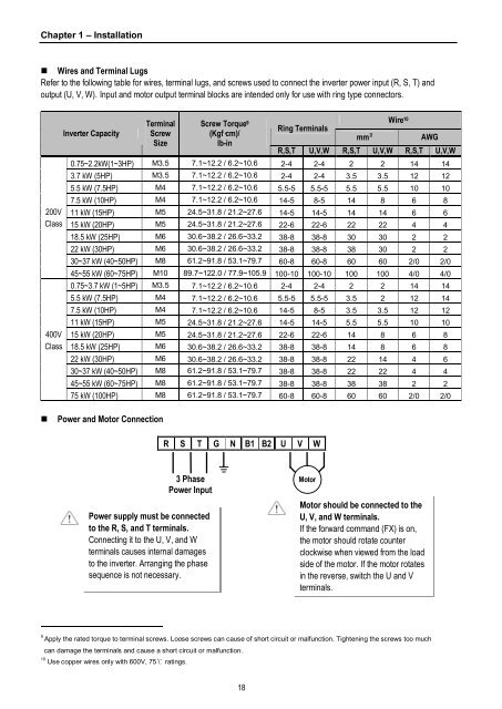
Chapter 1 – Installation• Wires and Terminal LugsRefer to the following table for wires, terminal lugs, and screws used to connect the inverter power input (R, S, T) andoutput (U, V, W). Input and motor output terminal blocks are intended only for use with ring type connectors.Inverter CapacityTerminalScrewSizeScrew Torque 9(Kgf·cm)/lb-inWire 10Ring Terminalsmm²AWGR,S,T U,V,W R,S,T U,V,W R,S,T U,V,W0.75~2.2kW(1~3HP) M3.5 7.1~12.2 / 6.2~10.6 2-4 2-4 2 2 14 143.7 kW (5HP) M3.5 7.1~12.2 / 6.2~10.6 2-4 2-4 3.5 3.5 12 12200VClass400VClass5.5 kW (7.5HP) M4 7.1~12.2 / 6.2~10.6 5.5-5 5.5-5 5.5 5.5 10 107.5 kW (10HP) M4 7.1~12.2 / 6.2~10.6 14-5 8-5 14 8 6 811 kW (15HP) M5 24.5~31.8 / 21.2~27.6 14-5 14-5 14 14 6 615 kW (20HP) M5 24.5~31.8 / 21.2~27.6 22-6 22-6 22 22 4 418.5 kW (25HP) M6 30.6~38.2 / 26.6~33.2 38-8 38-8 30 30 2 222 kW (30HP) M6 30.6~38.2 / 26.6~33.2 38-8 38-8 38 30 2 230~37 kW (40~50HP) M8 61.2~91.8 / 53.1~79.7 60-8 60-8 60 60 2/0 2/045~55 kW (60~75HP) M10 89.7~122.0 / 77.9~105.9 100-10 100-10 100 100 4/0 4/00.75~3.7 kW (1~5HP) M3.5 7.1~12.2 / 6.2~10.6 2-4 2-4 2 2 14 145.5 kW (7.5HP) M4 7.1~12.2 / 6.2~10.6 5.5-5 5.5-5 3.5 2 12 147.5 kW (10HP) M4 7.1~12.2 / 6.2~10.6 14-5 8-5 3.5 3.5 12 1211 kW (15HP) M5 24.5~31.8 / 21.2~27.6 14-5 14-5 5.5 5.5 10 1015 kW (20HP) M5 24.5~31.8 / 21.2~27.6 22-6 22-6 14 8 6 818.5 kW (25HP) M6 30.6~38.2 / 26.6~33.2 38-8 38-8 14 8 6 822 kW (30HP) M6 30.6~38.2 / 26.6~33.2 38-8 38-8 22 14 4 630~37 kW (40~50HP) M8 61.2~91.8 / 53.1~79.7 38-8 38-8 22 22 4 445~55 kW (60~75HP) M8 61.2~91.8 / 53.1~79.7 38-8 38-8 38 38 2 275 kW (100HP) M8 61.2~91.8 / 53.1~79.7 60-8 60-8 60 60 2/0 2/0• Power and Motor ConnectionR S T G N B1 B2 U V W3 PhasePower InputPower supply must be connectedto the R, S, and T terminals.Connecting it to the U, V, and Wterminals causes internal damagesto the inverter. Arranging the phasesequence is not necessary.MotorMotor should be connected to theU, V, and W terminals.If the forward command (FX) is on,the motor should rotate counterclockwise when viewed from the loadside of the motor. If the motor rotatesin the reverse, switch the U and Vterminals.9Apply the rated torque to terminal screws. Loose screws can cause of short circuit or malfunction. Tightening the screws too muchcan damage the terminals and cause a short circuit or malfunction.10Use copper wires only with 600V, 75℃ ratings.18