Manual - Famco
Manual - Famco
Manual - Famco
- No tags were found...

You also want an ePaper? Increase the reach of your titles
YUMPU automatically turns print PDFs into web optimized ePapers that Google loves.
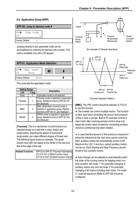
Chapter 6 - Parameter Description [APP]6.6 Application Group [APP]APP-00: Jump to desired code #ThreadAPP► Jump code00 1Factory Default: 1TraverseRotaryMotionTraverseReciprocation(Mechanical)Thread(ConstantSpeed)Jumping directly to any parameter code can beaccomplished by entering the desired code number. Thiscode is available only with LCD keypad.[An example of Traverse Operation]APP-01: Application Mode SelectionAPP► App. mode01 None01Factory Default: None 00APP-02Trv. AmpAPP-03Trv. ScrAPP-06Offset-HighReferenceSpeedAPP-07Offset-LowThis code sets the application mode.Setting RangeLCD 7-SegDescriptionNone 0 Application mode is not selected.Traverse 1Traverse mode is selected in applicationgroup. Related functions (APP-02~07)are displayed.MMC 2MMC (Multi-Motor Control) mode isselected in application group. Relatedfunctions (APP-08~31) are displayed.DRAW 3DRAW mode is selected in applicationgroup. Related functions (APP-32~33)are displayed.[Traverse]: This is a mechanism to wind thread to anintended shape on a reel with a rotary motion andreciprocation. Adjusting the speed of mechanicalreciprocation can make different shapes of thread reel.The following figure shows an example. The guideshould move with low speed at the center of the reel andfast at the edge of the reel.Related Functions:APP-02 to APP-07 [Traverse Parameters]I/O-12 to I/O-14 [Multi-Function Input]EXT-30 to EXT-32 [Multi-Function Output]APP-04Traverse AccAPP-05Traverse Dec[Traverse Operation Pattern][MMC]: The ‘PID’ control should be selected in FU2-47to use this function.¨ One inverter can control multiple motors. This functionis often used when controlling the amount and pressureof flow in fans or pumps. Built-in PI controller controls amain motor after receiving process control value andkeeps the control value constant by connecting auxiliarymotors to commercial line when needed.¨ In case that flow amount or flow pressure is beyond orbelow the reference so the main drive cannot control byitself, auxiliary motors are automatically turned on/off.Maximum four (Q1~3 and Aux. output) auxiliary motorscan be run. Each Starting and Stop Frequency shouldbe set to four auxiliary motors.¨ Auto Change can be selected to automatically switchthe order of the running motors for keeping motor runtimeconstant. Set mode ‘1’ for automatic changing ofauxiliary motors only and set mode ‘2’ for automaticchanging of all motors including main motor. For mode‘2’, external sequence (Refer to APP-26) should beconfigured.145