Manual - Famco
Manual - Famco
Manual - Famco
- No tags were found...

Create successful ePaper yourself
Turn your PDF publications into a flip-book with our unique Google optimized e-Paper software.
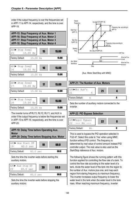
Chapter 6 - Parameter Description [APP]order if the output frequency is over the frequencies setin APP-11 to APP-14, respectively, and the time is overAPP-19.APP-15: Stop Frequency of Aux. Motor 1APP-16: Stop Frequency of Aux. Motor 2APP-17: Stop Frequency of Aux. Motor 3APP-18: Stop Frequency of Aux. Motor 4APP► Stop freq115 15.00 Hz1515.00OutputFrequencyStart freq 1(APP-11)Stop freq1(APP-15)StartingFreq.Aux start DT(APP-19)Aux stop DT(APP-20)Frequency rise according toAPP-19Frequency drop according toAPP-20FlowFactory Default: 15.00 Hz 15.00APP► Stop freq216 15.00 Hz1615.00Factory Default: 15.00 Hz 15.00Aux. MotorStart/StopStopStart[Aux. Motor Start/Stop with MMC]When the FlowincreseWhen the FlowdecreaseAPP► Stop freq317 15.00 Hz15.00Factory Default: 15.00 Hz 15.0017APP-21: The Number of Aux. MotorsAPP►Nbr Aux’s21 4214APP► Stop freq418 15.00 Hz15.00Factory Default: 15.00 Hz 15.0018Factory Default: 4 4Sets the number of auxiliary motors connected to theinverter.The inverter turns off RLY3, RLY2, RLY1, and AUX inorder if the output frequency is below the frequencies setin APP-15 to APP-18, respectively, and the time is overAPP-20.APP-22: PID Bypass SelectionAPP►Regul Bypass22 --- No ---220APP-19: Delay Time before Operating Aux.MotorAPP-20: Delay Time before Stopping Aux. MotorAPP► Aux Start DT19 60.0 sec19Sets the time the inverter waits before starting theauxiliary motors.60.0Factory Default: 60.0 sec 60.0APP► Aux Stop DT20 60.0 sec2060.0Factory Default: 60.0 sec 60.0Sets the time the inverter waits before stopping theauxiliary motors.Factory Default: No 0This is used to bypass the PID operation selected inFU2-47. Select this code to ‘Yes’ when using MMCfunction without PID control. The frequency isdetermined by real value of control amount instead PIDcontroller output. The real value is also used as theStart/Stop reference of Aux. motors.The following figure shows the running pattern with thisfunction applied for controlling the flow rate of a tank. Tocontrol the flow rate according to the water level of atank, divide the water level of the tank into the region tothe number of Aux. motors plus one, and map eachregion from staring frequency to maximum frequency.The inverter increases output frequency to lower thewater level in the tank when the water level in the tankrises. When reaching maximum frequency, inverter148