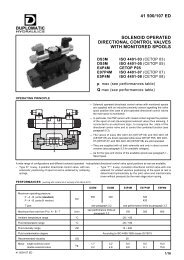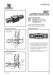
Manual - Famco
Manual - Famco
Manual - Famco
- No tags were found...

You also want an ePaper? Increase the reach of your titles
YUMPU automatically turns print PDFs into web optimized ePapers that Google loves.
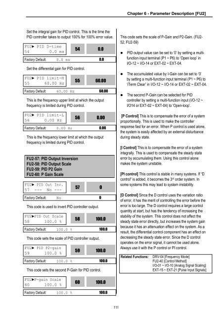
Chapter 6 - Parameter Description [FU2]Set the integral gain for PID control. This is the time thePID controller takes to output 100% for 100% error value.FU2► PID D-time54 0.0 ms54Set the differential gain for PID control.This is the frequency upper limit at which the outputfrequency is limited during PID control.This is the frequency lower limit at which the outputfrequency is limited during PID control.FU2-57: PID Output InversionFU2-58: PID Output ScaleFU2-59: PID P2 GainFU2-60: P Gain ScaleThis code is used to invert PID controller output.This code sets the scale of PID controller output.This code sets the second P-Gain for PID control.0.0Factory Default: 0.0 ms 0.0FU2► PID limit-H55 60.00 Hz5560.00Factory Default: 60.00 Hz 60.00FU2► PID limit-L56 0.00 Hz560.00Factory Default: 0.00 Hz 0.00FU2► PID Out Inv.57 --- No ---57Factory Default: No 0FU2►PID Out Scale58 100.0 %580100.0Factory Default: 100.0 % 100.0FU2► PID P2-gain59 100.0 %59100.0Factory Default: 100.0 % 100.0This code sets the scale of P-Gain and P2-Gain. (FU2-52, FU2-59)• PID output value can be set to ‘0’ by setting a multifunctioninput terminal (P1 ~ P6) to ‘Open loop’ inI/O-12 ~ I/O-14 or EXT-02 ~ EXT-04.• The accumulated value by I-Gain can be set to ‘0’by setting a multi-function input terminal (P1 ~ P6) to‘iTerm Clear’ in I/O-12 ~ I/O-14 or EXT-02 ~ EXT-04.• The second P-Gain can be selected for PIDcontroller by setting a multi-function input (I/O-12 ~I/O14 or EXT-02 ~ EXT-04) to ‘Open-loop’.[P Control] This is to compensate the error of a systemproportionally. This is used to make the controllerresponse fast for an error. When P control is used alone,the system is easily affected by an external disturbanceduring steady state.[I Control] This is to compensate the error of a systemintegrally. This is used to compensate the steady stateerror by accumulating them. Using this control alonemakes the system unstable.[PI control] This control is stable in many systems. If “Dcontrol” is added, it becomes the 3 rd order system. Insome systems this may lead to system instability.[D Control] Since the D control uses the variation ratioof error, it has the merit of controlling the error before theerror is too large. The D control requires a large controlquantity at start, but has the tendency of increasing thestability of the system. This control does not affect thesteady state error directly, but increases the system gainbecause it has an attenuation effect on the system. As aresult, the differential control component has an effect ondecreasing the steady state error. Since the D controloperates on the error signal, it cannot be used alone.Always use it with the P control or PI control.Related Functions:DRV-04 [Frequency Mode]FU2-40 [Control Method]I/O-01 ~ I/O-10 [Analog Signal Scaling]EXT-15 ~ EXT-21 [Pulse Input Signals]FU2►P-gain Scale60 100.0 %60100.0Factory Default: 100.0 % 100.0111