Manual - Famco
Manual - Famco
Manual - Famco
- No tags were found...

You also want an ePaper? Increase the reach of your titles
YUMPU automatically turns print PDFs into web optimized ePapers that Google loves.
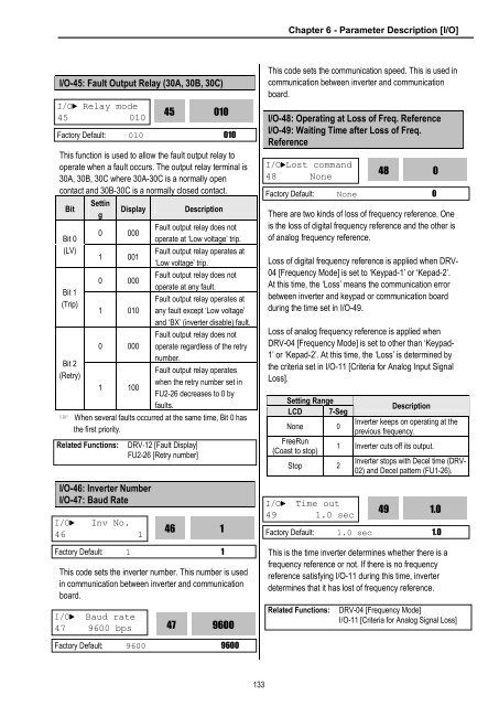
Chapter 6 - Parameter Description [I/O]I/O-45: Fault Output Relay (30A, 30B, 30C)I/O► Relay mode45 010This function is used to allow the fault output relay tooperate when a fault occurs. The output relay terminal is30A, 30B, 30C where 30A-30C is a normally opencontact and 30B-30C is a normally closed contact.BitBit 0(LV)Bit 1(Trip)Bit 2(Retry)SettingDisplay0 0001 0010 0001 0100 0001 100DescriptionFault output relay does notoperate at ‘Low voltage’ trip.Fault output relay operates at‘Low voltage’ trip.Fault output relay does notoperate at any fault.Fault output relay operates atany fault except ‘Low voltage’and ‘BX’ (inverter disable) fault.Fault output relay does notoperate regardless of the retrynumber.Fault output relay operateswhen the retry number set inFU2-26 decreases to 0 byfaults.☞ When several faults occurred at the same time, Bit 0 hasthe first priority.I/O-46: Inverter NumberI/O-47: Baud Rate45010Factory Default: 010 010Related Functions:I/O► Inv No.46 1DRV-12 [Fault Display]FU2-26 [Retry number]46Factory Default: 1 1This code sets the inverter number. This number is usedin communication between inverter and communicationboard.I/O► Baud rate47 9600 bps 4796001This code sets the communication speed. This is used incommunication between inverter and communicationboard.I/O-48: Operating at Loss of Freq. ReferenceI/O-49: Waiting Time after Loss of Freq.ReferenceI/O►Lost command48 NoneThere are two kinds of loss of frequency reference. Oneis the loss of digital frequency reference and the other isof analog frequency reference.Loss of digital frequency reference is applied when DRV-04 [Frequency Mode] is set to ‘Keypad-1’ or ‘Kepad-2’.At this time, the ‘Loss’ means the communication errorbetween inverter and keypad or communication boardduring the time set in I/O-49.Loss of analog frequency reference is applied whenDRV-04 [Frequency Mode] is set to other than ‘Keypad-1’ or ‘Kepad-2’. At this time, the ‘Loss’ is determined bythe criteria set in I/O-11 [Criteria for Analog Input SignalLoss].Setting RangeLCD 7-SegNone 0FreeRun(Coast to stop)Stop 248Factory Default: None 0I/O► Time out49 1.0 secDescriptionInverter keeps on operating at theprevious frequency.1 Inverter cuts off its output.Inverter stops with Decel time (DRV-02) and Decel pattern (FU1-26).49This is the time inverter determines whether there is afrequency reference or not. If there is no frequencyreference satisfying I/O-11 during this time, inverterdetermines that it has lost of frequency reference.01.0Factory Default: 1.0 sec 1.0Related Functions:DRV-04 [Frequency Mode]I/O-11 [Criteria for Analog Signal Loss]Factory Default: 9600 9600133