Manual - Famco
Manual - Famco
Manual - Famco
- No tags were found...

You also want an ePaper? Increase the reach of your titles
YUMPU automatically turns print PDFs into web optimized ePapers that Google loves.
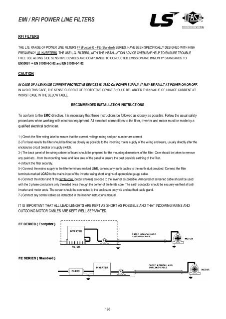
EMI / RFI POWER LINE FILTERSRFI FILTERSTHE L.G. RANGE OF POWER LINE FILTERS FF (Footprint) – FE (Standard) SERIES, HAVE BEEN SPECIFICALLY DESIGNED WITH HIGHFREQUENCY LS INVERTERS, THE USE L.G. FILTERS, WITH THE INSTALLATION ADVICE OVERLEAF HELP TO ENSURE TROUBLEFREE USE ALONG SIDE SENSITIVE DEVICES AND COMPLIANCE TO CONDUCTED EMISSION AND IMMUNITY STANDARDS TOEN50081 -> EN 61000-6-3:02 and EN 61000-6-1:02CAUTIONIN CASE OF A LEAKAGE CURRENT PROTECTIVE DEVICES IS USED ON POWER SUPPLY, IT MAY BE FAULT AT POWER-ON OR OFF.IN AVOID THIS CASE, THE SENSE CURRENT OF PROTECTIVE DEVICE SHOULD BE LARGER THAN VALUE OF LAKAGE CURRENT ATWORST CASE IN THE BELOW TABLE.RECOMMENDED INSTALLATION INSTRUCTIONSTo conform to the EMC directive, it is necessary that these instructions be followed as closely as possible. Follow the usual safetyprocedures when working with electrical equipment. All electrical connections to the filter, inverter and motor must be made by aqualified electrical technician.1-) Check the filter rating label to ensure that the current, voltage rating and part number are correct.2-) For best results the filter should be fitted as closely as possible to the incoming mains supply of the wiring enclosure, usually directly after theenclosures circuit breaker or supply switch.3-) The back panel of the wiring cabinet of board should be prepared for the mounting dimensions of the filter. Care should be taken to removeany paint etc... from the mounting holes and face area of the panel to ensure the best possible earthing of the filter.4-) Mount the filter securely.5-) Connect the mains supply to the filter terminals marked LINE, connect any earth cables to the earth stud provided. Connect the filterterminals marked LOAD to the mains input of the inverter using short lengths of appropriate gauge cable.6-) Connect the motor and fit the ferrite core (output chokes) as close to the inverter as possible. Armoured or screened cable should be usedwith the 3 phase conductors only threaded twice through the center of the ferrite core. The earth conductor should be securely earthed at bothinverter and motor ends. The screen should be connected to the enclosure body via and earthed cable gland.7-) Connect any control cables as instructed in the inverter instructions manual.IT IS IMPORTANT THAT ALL LEAD LENGHTS ARE KEPT AS SHORT AS POSSIBLE AND THAT INCOMING MAINS ANDOUTGOING MOTOR CABLES ARE KEPT WELL SEPARATED.196