Manual - Famco
Manual - Famco
Manual - Famco
- No tags were found...

You also want an ePaper? Increase the reach of your titles
YUMPU automatically turns print PDFs into web optimized ePapers that Google loves.
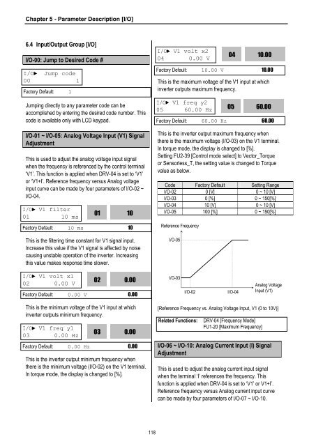
Chapter 5 - Parameter Description [I/O]6.4 Input/Output Group [I/O]I/O-00: Jump to Desired Code #I/O► Jump code00 1Factory Default: 1Jumping directly to any parameter code can beaccomplished by entering the desired code number. Thiscode is available only with LCD keypad.I/O-01 ~ I/O-05: Analog Voltage Input (V1) SignalAdjustmentThis is used to adjust the analog voltage input signalwhen the frequency is referenced by the control terminal‘V1’. This function is applied when DRV-04 is set to ‘V1’or ‘V1+I’. Reference frequency versus Analog voltageinput curve can be made by four parameters of I/O-02 ~I/O-04.I/O► V1 filter01 10 ms01This is the filtering time constant for V1 signal input.Increase this value if the V1 signal is affected by noisecausing unstable operation of the inverter. Increasingthis value makes response time slower.10Factory Default: 10 ms 10I/O► V1 volt x204 0.00 V0410.00Factory Default: 10.00 V 10.00This is the maximum voltage of the V1 input at whichinverter outputs maximum frequency.I/O► V1 freq y205 60.00 Hz0560.00Factory Default: 60.00 Hz 60.00This is the inverter output maximum frequency whenthere is the maximum voltage (I/O-03) on the V1 terminal.In torque mode, the display is changed to [%].Setting FU2-39 [Control mode select] to Vector_Torqueor Sensorless_T, the setting value is changed to Torquevalue as below.Code Factory Default Setting RangeI/O-02 0 [V] 0 ~ 10 [V]I/O-03 0 [%] 0 ~ 150[%]I/O-04 10 [V] 0 ~ 10 [V]I/O-05 100 [%] 0 ~ 150[%]Reference FrequencyI/O-05I/O► V1 volt x102 0.00 V020.00Factory Default: 0.00 V 0.00I/O-03I/O-02I/O-04Analog VoltageInput (V1)This is the minimum voltage of the V1 input at whichinverter outputs minimum frequency.I/O► V1 freq y103 0.00 Hz030.00Factory Default: 0.00 Hz 0.00This is the inverter output minimum frequency whenthere is the minimum voltage (I/O-02) on the V1 terminal.In torque mode, the display is changed to [%].[Reference Frequency vs. Analog Voltage Input, V1 (0 to 10V)]Related Functions:DRV-04 [Frequency Mode]FU1-20 [Maximum Frequency]I/O-06 ~ I/O-10: Analog Current Input (I) SignalAdjustmentThis is used to adjust the analog current input signalwhen the terminal ‘I’ references the frequency. Thisfunction is applied when DRV-04 is set to ‘V1’ or V1+I’.Reference frequency versus Analog current input curvecan be made by four parameters of I/O-07 ~ I/O-10.118