Masoneilan SVI II AP Installation and Maintenance ... - GE Energy
Masoneilan SVI II AP Installation and Maintenance ... - GE Energy
Masoneilan SVI II AP Installation and Maintenance ... - GE Energy

You also want an ePaper? Increase the reach of your titles
YUMPU automatically turns print PDFs into web optimized ePapers that Google loves.
Rotary - 90°<br />
<strong>Installation</strong> <strong>and</strong> Set Up<br />
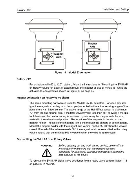
Figure 10<br />
Model 33 Actuator<br />
Rotary - 90°<br />
For actuators with 60 to 120° rotation, follow the instructions in “Mounting the <strong>SVI</strong> <strong>II</strong> <strong>AP</strong><br />
on Rotary Valves” on page 31 except mount the magnet at plus or minus 45° while the<br />
actuator de-energized as shown in Figure 10 on page 35.<br />
Magnet Orientation on Rotary Valve Shafts<br />
The same mounting hardware is used for Models 35, 30 actuators. For each actuator<br />
type the magnetic coupling must be properly oriented to the active sensing angle of the<br />
positioners Hall Effect sensor. The active range of the Hall-Effect sensor is plus⁄minus<br />
70° from the null magnet axis. If the total valve travel is less than 60°, allowing a margin<br />
for tolerances, the best accuracy is achieved by mounting the magnet with the axis<br />
vertical in the valve-closed position. The location of the magnets in the ring of the<br />
magnet holder. The axis of the magnets is the line through the centers of both magnets.<br />
Mount the magnet holder with the magnet axis vertical on the 35, 30 when the valve is<br />
closed. If travel of the valve exceeds 60°, the magnet must be assembled to the rotary<br />
valve shaft so that the magnet axis is vertical when the valve is at mid-scale.<br />
Dismantling the <strong>SVI</strong> <strong>II</strong> <strong>AP</strong> from Rotary Valves<br />
WARNING<br />
Before carrying out any work on the device, power off the<br />
instrument or make sure that the device’s location<br />
conditions for potentially explosive atmosphere permit the<br />
safe opening of the cover.<br />
To remove the <strong>SVI</strong> <strong>II</strong> <strong>AP</strong> digital valve positioner from a rotary valve perform Steps 1 - 8<br />
on page 28 in reverse.<br />
35