Masoneilan SVI II AP Installation and Maintenance ... - GE Energy
Masoneilan SVI II AP Installation and Maintenance ... - GE Energy
Masoneilan SVI II AP Installation and Maintenance ... - GE Energy

Create successful ePaper yourself
Turn your PDF publications into a flip-book with our unique Google optimized e-Paper software.
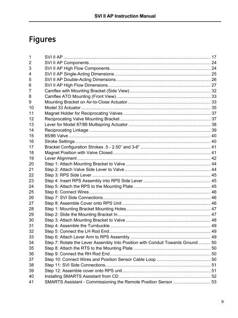
<strong>SVI</strong> <strong>II</strong> <strong>AP</strong> Instruction Manual<br />
Figures<br />
1 <strong>SVI</strong> <strong>II</strong> <strong>AP</strong> ........................................................................................................................ 17<br />
2 <strong>SVI</strong> <strong>II</strong> <strong>AP</strong> Components ................................................................................................... 24<br />
3 <strong>SVI</strong> <strong>II</strong> <strong>AP</strong> High Flow Components .................................................................................. 24<br />
4 <strong>SVI</strong> <strong>II</strong> <strong>AP</strong> Single-Acting Dimensions .............................................................................. 25<br />
5 <strong>SVI</strong> <strong>II</strong> <strong>AP</strong> Double-Acting Dimensions ............................................................................. 26<br />
6 <strong>SVI</strong> <strong>II</strong> <strong>AP</strong> High Flow Dimensions.................................................................................... 27<br />
7 Camflex with Mounting Bracket (Side View) .................................................................. 32<br />
8 Camflex ATO Mounting (Front View) ............................................................................. 33<br />
9 Mounting Bracket on Air-to-Close Actuator.................................................................... 33<br />
10 Model 33 Actuator.......................................................................................................... 35<br />
11 Magnet Holder for Reciprocating Valves ....................................................................... 37<br />
12 Reciprocating Valve Mounting Bracket .......................................................................... 37<br />
13 Lever for Model 87/88 Multispring Actuator ................................................................... 38<br />
14 Reciprocating Linkage ................................................................................................... 39<br />
15 85/86 Valve .................................................................................................................... 40<br />
16 Stroke Settings...............................................................................................................40<br />
17 Bracket Configuration Strokes .5 - 2.50” <strong>and</strong> 3-6” ......................................................... 41<br />
18 Magnet Position with Valve Closed................................................................................ 41<br />
19 Lever Alignment ............................................................................................................. 42<br />
20 Step 1: Attach Mounting Bracket to Valve ..................................................................... 44<br />
21 Step 2: Attach Valve Side Lever to Valve ...................................................................... 44<br />
22 Step 3: RPS Side Lever ................................................................................................. 45<br />
23 Step 4: Insert RPS Assembly into RPS Side Lever ....................................................... 45<br />
24 Step 5: Attach the RPS to the Mounting Plate ............................................................... 45<br />
25 Step 6: Connect Wires ................................................................................................... 46<br />
26 Step 7: <strong>SVI</strong> Side Connections........................................................................................ 46<br />
27 Step 8: Assemble Cover onto RPS Unit ........................................................................ 46<br />
28 Step 1: Mounting Bracket Mounting Holes..................................................................... 47<br />
29 Step 2: Slide the Mounting Bracket In............................................................................ 47<br />
30 Step 3: Attach Mounting Bracket to Valve ..................................................................... 48<br />
31 Step 4: Assemble the Turnbuckle .................................................................................. 49<br />
32 Step 5: Connect the LH Rod End................................................................................... 49<br />
33 Step 6: Attach Lever Arm to RPS Assembly.................................................................. 49<br />
34 Step 7: Rotate the Lever Assembly Into Position with Conduit Towards Ground .......... 50<br />
35 Step 8: Attach the RTS to the Mounting Plate ............................................................... 50<br />
36 Step 9: Connect the RH Rod End .................................................................................. 50<br />
37 Step 10: Connect Wires <strong>and</strong> Position Sensor Cable Loop ............................................ 50<br />
38 Step 11: <strong>SVI</strong> Side Connections...................................................................................... 51<br />
39 Step 12: Assemble cover onto RPS unit........................................................................ 51<br />
40 Installing SMARTS Assistant from CD........................................................................... 52<br />
41 SMARTS Assistant - Commissioning the Remote Position Sensor............................... 53<br />
9