Masoneilan SVI II AP Installation and Maintenance ... - GE Energy
Masoneilan SVI II AP Installation and Maintenance ... - GE Energy
Masoneilan SVI II AP Installation and Maintenance ... - GE Energy

Create successful ePaper yourself
Turn your PDF publications into a flip-book with our unique Google optimized e-Paper software.
Installing the <strong>SVI</strong> <strong>II</strong> <strong>AP</strong> Remote<br />
<strong>Installation</strong> <strong>and</strong> Set Up<br />
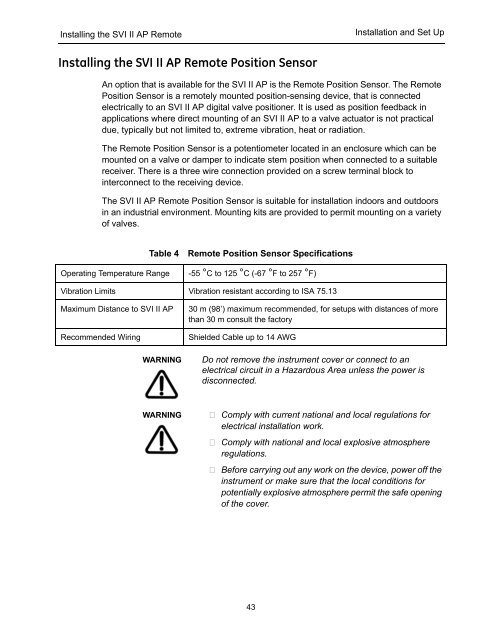
Installing the <strong>SVI</strong> <strong>II</strong> <strong>AP</strong> Remote Position Sensor<br />
An option that is available for the <strong>SVI</strong> <strong>II</strong> <strong>AP</strong> is the Remote Position Sensor. The Remote<br />
Position Sensor is a remotely mounted position-sensing device, that is connected<br />
electrically to an <strong>SVI</strong> <strong>II</strong> <strong>AP</strong> digital valve positioner. It is used as position feedback in<br />
applications where direct mounting of an <strong>SVI</strong> <strong>II</strong> <strong>AP</strong> to a valve actuator is not practical<br />
due, typically but not limited to, extreme vibration, heat or radiation.<br />
The Remote Position Sensor is a potentiometer located in an enclosure which can be<br />
mounted on a valve or damper to indicate stem position when connected to a suitable<br />
receiver. There is a three wire connection provided on a screw terminal block to<br />
interconnect to the receiving device.<br />
The <strong>SVI</strong> <strong>II</strong> <strong>AP</strong> Remote Position Sensor is suitable for installation indoors <strong>and</strong> outdoors<br />
in an industrial environment. Mounting kits are provided to permit mounting on a variety<br />
of valves.<br />
Table 4<br />
Operating Temperature Range<br />
Remote Position Sensor Specifications<br />
-55 °C to 125 °C (-67 °F to 257 °F)<br />
Vibration Limits Vibration resistant according to ISA 75.13<br />
Maximum Distance to <strong>SVI</strong> <strong>II</strong> <strong>AP</strong><br />
Recommended Wiring<br />
WARNING<br />
30 m (98’) maximum recommended, for setups with distances of more<br />
than 30 m consult the factory<br />
Shielded Cable up to 14 AWG<br />
Do not remove the instrument cover or connect to an<br />
electrical circuit in a Hazardous Area unless the power is<br />
disconnected.<br />
WARNING<br />
Comply with current national <strong>and</strong> local regulations for<br />
electrical installation work.<br />
Comply with national <strong>and</strong> local explosive atmosphere<br />
regulations.<br />
Before carrying out any work on the device, power off the<br />
instrument or make sure that the local conditions for<br />
potentially explosive atmosphere permit the safe opening<br />
of the cover.<br />
43