

Agilent Spectrum Analysis Basics - Agilent Technologies
Agilent Spectrum Analysis Basics - Agilent Technologies
Agilent Spectrum Analysis Basics - Agilent Technologies

You also want an ePaper? Increase the reach of your titles
YUMPU automatically turns print PDFs into web optimized ePapers that Google loves.
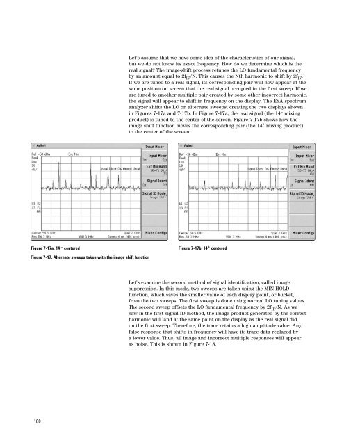
Let’s assume that we have some idea of the characteristics of our signal,<br />
but we do not know its exact frequency. How do we determine which is the<br />
real signal? The image-shift process retunes the LO fundamental frequency<br />
by an amount equal to 2f IF /N. This causes the Nth harmonic to shift by 2f IF .<br />
If we are tuned to a real signal, its corresponding pair will now appear at the<br />
same position on screen that the real signal occupied in the first sweep. If we<br />
are tuned to another multiple pair created by some other incorrect harmonic,<br />
the signal will appear to shift in frequency on the display. The ESA spectrum<br />
analyzer shifts the LO on alternate sweeps, creating the two displays shown<br />
in Figures 7-17a and 7-17b. In Figure 7-17a, the real signal (the 14 – mixing<br />
product) is tuned to the center of the screen. Figure 7-17b shows how the<br />
image shift function moves the corresponding pair (the 14 + mixing product)<br />
to the center of the screen.<br />
Figure 7-17a. 14 – centered<br />
Figure 7-17b. 14 + centered<br />
Figure 7-17. Alternate sweeps taken with the image shift function<br />
Let’s examine the second method of signal identification, called image<br />
suppression. In this mode, two sweeps are taken using the MIN HOLD<br />
function, which saves the smaller value of each display point, or bucket,<br />
from the two sweeps. The first sweep is done using normal LO tuning values.<br />
The second sweep offsets the LO fundamental frequency by 2f IF /N. As we<br />
saw in the first signal ID method, the image product generated by the correct<br />
harmonic will land at the same point on the display as the real signal did<br />
on the first sweep. Therefore, the trace retains a high amplitude value. Any<br />
false response that shifts in frequency will have its trace data replaced by<br />
a lower value. Thus, all image and incorrect multiple responses will appear<br />
as noise. This is shown in Figure 7-18.<br />
100


