

Agilent Spectrum Analysis Basics - Agilent Technologies
Agilent Spectrum Analysis Basics - Agilent Technologies
Agilent Spectrum Analysis Basics - Agilent Technologies

Create successful ePaper yourself
Turn your PDF publications into a flip-book with our unique Google optimized e-Paper software.
Digital modulation analysis<br />
The common wireless communication systems used throughout the world<br />
today all have prescribed measurement techniques defined by standardsdevelopment<br />
organizations and governmental regulatory bodies. Optional<br />
measurement personalities are commonly available on spectrum analyzers<br />
to perform the key tests defined for a particular communication format.<br />
For example, if we need to test a transmitter to the Bluetooth wireless<br />
communication standard, we must measure parameters such as:<br />
• Average/peak output power<br />
• Modulation characteristics<br />
• Initial carrier frequency tolerance<br />
• Carrier frequency drift<br />
• Monitor band/channel<br />
• Modulation overview<br />
• Output spectrum<br />
• 20 dB bandwidth<br />
• Adjacent channel power<br />
These measurements are available on the <strong>Agilent</strong> ESA-E Series spectrum<br />
analyzer with appropriate options. For more information on Bluetooth<br />
measurements, please refer to <strong>Agilent</strong> Application Note 1333, Performing<br />
Bluetooth RF Measurements Today, literature number 5968-7746E. Other<br />
communication standards-based measurement personalities available on<br />
the ESA-E Series include cdmaOne and GSM/GPRS/EDGE.<br />
Measurement capabilities for a wide variety of wireless communications<br />
standards are also available for the PSA Series spectrum analyzers.<br />
Optional measurement personalities include:<br />
• GSM/EDGE<br />
• W-CDMA<br />
•HSDPA<br />
• cdma2000<br />
• 1xEV-DO<br />
• 1xEV-DV<br />
• cdmaOne<br />
• NADC and PDC<br />
• TD-SCDMA<br />
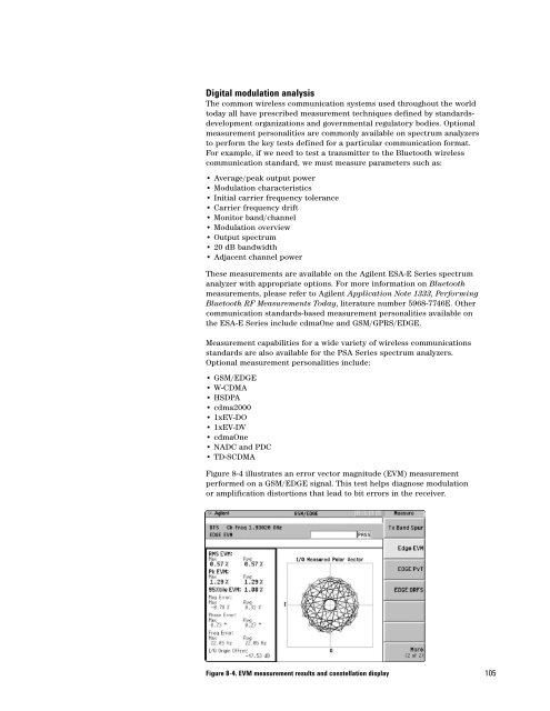
Figure 8-4 illustrates an error vector magnitude (EVM) measurement<br />
performed on a GSM/EDGE signal. This test helps diagnose modulation<br />
or amplification distortions that lead to bit errors in the receiver.<br />
Figure 8-4. EVM measurement results and constellation display<br />
105


