Agilent Spectrum Analysis Basics - Agilent Technologies
Agilent Spectrum Analysis Basics - Agilent Technologies
Agilent Spectrum Analysis Basics - Agilent Technologies
Create successful ePaper yourself
Turn your PDF publications into a flip-book with our unique Google optimized e-Paper software.
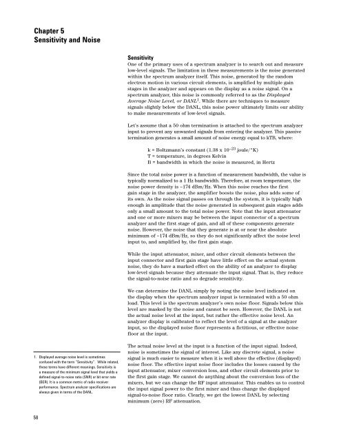
Chapter 5<br />
Sensitivity and Noise<br />
Sensitivity<br />
One of the primary uses of a spectrum analyzer is to search out and measure<br />
low-level signals. The limitation in these measurements is the noise generated<br />
within the spectrum analyzer itself. This noise, generated by the random<br />
electron motion in various circuit elements, is amplified by multiple gain<br />
stages in the analyzer and appears on the display as a noise signal. On a<br />
spectrum analyzer, this noise is commonly referred to as the Displayed<br />
Average Noise Level, or DANL 1 . While there are techniques to measure<br />
signals slightly below the DANL, this noise power ultimately limits our ability<br />
to make measurements of low-level signals.<br />
Let’s assume that a 50 ohm termination is attached to the spectrum analyzer<br />
input to prevent any unwanted signals from entering the analyzer. This passive<br />
termination generates a small amount of noise energy equal to kTB, where:<br />
k = Boltzmann’s constant (1.38 x 10 –23 joule/°K)<br />
T = temperature, in degrees Kelvin<br />
B = bandwidth in which the noise is measured, in Hertz<br />
Since the total noise power is a function of measurement bandwidth, the value is<br />
typically normalized to a 1 Hz bandwidth. Therefore, at room temperature, the<br />
noise power density is –174 dBm/Hz. When this noise reaches the first<br />
gain stage in the analyzer, the amplifier boosts the noise, plus adds some of<br />
its own. As the noise signal passes on through the system, it is typically high<br />
enough in amplitude that the noise generated in subsequent gain stages adds<br />
only a small amount to the total noise power. Note that the input attenuator<br />
and one or more mixers may be between the input connector of a spectrum<br />
analyzer and the first stage of gain, and all of these components generate<br />
noise. However, the noise that they generate is at or near the absolute<br />
minimum of –174 dBm/Hz, so they do not significantly affect the noise level<br />
input to, and amplified by, the first gain stage.<br />
While the input attenuator, mixer, and other circuit elements between the<br />
input connector and first gain stage have little effect on the actual system<br />
noise, they do have a marked effect on the ability of an analyzer to display<br />
low-level signals because they attenuate the input signal. That is, they reduce<br />
the signal-to-noise ratio and so degrade sensitivity.<br />
We can determine the DANL simply by noting the noise level indicated on<br />
the display when the spectrum analyzer input is terminated with a 50 ohm<br />
load. This level is the spectrum analyzer’s own noise floor. Signals below this<br />
level are masked by the noise and cannot be seen. However, the DANL is not<br />
the actual noise level at the input, but rather the effective noise level. An<br />
analyzer display is calibrated to reflect the level of a signal at the analyzer<br />
input, so the displayed noise floor represents a fictitious, or effective noise<br />
floor at the input.<br />
1. Displayed average noise level is sometimes<br />
confused with the term “Sensitivity”. While related,<br />
these terms have different meanings. Sensitivity is<br />
a measure of the minimum signal level that yields a<br />
defined signal-to-noise ratio (SNR) or bit error rate<br />
(BER). It is a common metric of radio receiver<br />
performance. <strong>Spectrum</strong> analyzer specifications are<br />
always given in terms of the DANL.<br />
The actual noise level at the input is a function of the input signal. Indeed,<br />
noise is sometimes the signal of interest. Like any discrete signal, a noise<br />
signal is much easier to measure when it is well above the effective (displayed)<br />
noise floor. The effective input noise floor includes the losses caused by the<br />
input attenuator, mixer conversion loss, and other circuit elements prior to<br />
the first gain stage. We cannot do anything about the conversion loss of the<br />
mixers, but we can change the RF input attenuator. This enables us to control<br />
the input signal power to the first mixer and thus change the displayed<br />
signal-to-noise floor ratio. Clearly, we get the lowest DANL by selecting<br />
minimum (zero) RF attenuation.<br />
58


