Agilent Spectrum Analysis Basics - Agilent Technologies
Agilent Spectrum Analysis Basics - Agilent Technologies
Agilent Spectrum Analysis Basics - Agilent Technologies
You also want an ePaper? Increase the reach of your titles
YUMPU automatically turns print PDFs into web optimized ePapers that Google loves.
Chapter 6<br />
Dynamic Range<br />
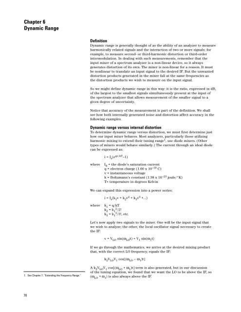
Definition<br />
Dynamic range is generally thought of as the ability of an analyzer to measure<br />
harmonically related signals and the interaction of two or more signals; for<br />
example, to measure second- or third-harmonic distortion or third-order<br />
intermodulation. In dealing with such measurements, remember that the<br />
input mixer of a spectrum analyzer is a non-linear device, so it always<br />
generates distortion of its own. The mixer is non-linear for a reason. It must<br />
be nonlinear to translate an input signal to the desired IF. But the unwanted<br />
distortion products generated in the mixer fall at the same frequencies as<br />
the distortion products we wish to measure on the input signal.<br />
So we might define dynamic range in this way: it is the ratio, expressed in dB,<br />
of the largest to the smallest signals simultaneously present at the input of<br />
the spectrum analyzer that allows measurement of the smaller signal to a<br />
given degree of uncertainty.<br />
Notice that accuracy of the measurement is part of the definition. We shall<br />
see how both internally generated noise and distortion affect accuracy in the<br />
following examples.<br />
Dynamic range versus internal distortion<br />
To determine dynamic range versus distortion, we must first determine just<br />
how our input mixer behaves. Most analyzers, particularly those utilizing<br />
harmonic mixing to extend their tuning range 1 , use diode mixers. (Other<br />
types of mixers would behave similarly.) The current through an ideal diode<br />
can be expressed as:<br />
i = I s (e qv/kT –1)<br />
where<br />
I S = the diode’s saturation current<br />
q = electron charge (1.60 x 10 –19 C)<br />
v = instantaneous voltage<br />
k = Boltzmann’s constant (1.38 x 10 –23 joule/°K)<br />
T= temperature in degrees Kelvin<br />
We can expand this expression into a power series:<br />
i = I s (k 1 v + k 2 v 2 + k 3 v 3 +...)<br />
where<br />
k 1 = q/kT<br />
k 2 = k 1 2 /2!<br />
k 3 = k 1 3 /3!, etc.<br />
Let’s now apply two signals to the mixer. One will be the input signal that<br />
we wish to analyze; the other, the local oscillator signal necessary to create<br />
the IF:<br />
v = V LO sin(ω LO t) + V 1 sin(ω 1 t)<br />
If we go through the mathematics, we arrive at the desired mixing product<br />
that, with the correct LO frequency, equals the IF:<br />
k 2 V LO V 1 cos[(ω LO – ω 1 )t]<br />
1. See Chapter 7, “Extending the Frequency Range.”<br />
A k 2 V LO V 1 cos[(ω LO + ω 1 )t] term is also generated, but in our discussion<br />
of the tuning equation, we found that we want the LO to be above the IF, so<br />
(ω LO + ω 1 ) is also always above the IF.<br />
70


