

Agilent Spectrum Analysis Basics - Agilent Technologies
Agilent Spectrum Analysis Basics - Agilent Technologies
Agilent Spectrum Analysis Basics - Agilent Technologies

Create successful ePaper yourself
Turn your PDF publications into a flip-book with our unique Google optimized e-Paper software.
Chapter 4<br />
Amplitude and<br />
Frequency Accuracy<br />
Now that we can view our signal on the display screen, let’s look at amplitude<br />
accuracy, or perhaps better, amplitude uncertainty. Most spectrum analyzers<br />
are specified in terms of both absolute and relative accuracy. However,<br />
relative performance affects both, so let’s look at those factors affecting<br />
relative measurement uncertainty first.<br />
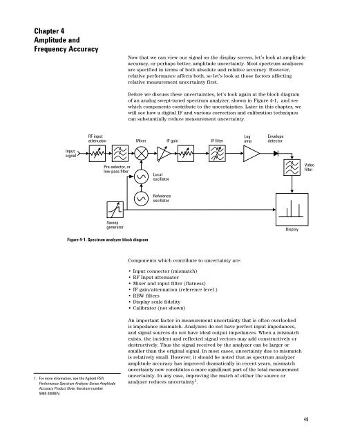
Before we discuss these uncertainties, let’s look again at the block diagram<br />
of an analog swept-tuned spectrum analyzer, shown in Figure 4-1, and see<br />
which components contribute to the uncertainties. Later in this chapter, we<br />
will see how a digital IF and various correction and calibration techniques<br />
can substantially reduce measurement uncertainty.<br />
RF input<br />
attenuator Mixer IF gain<br />
IF filter<br />
Log<br />
amp<br />
Envelope<br />
detector<br />
Input<br />
signal<br />
Pre-selector, or<br />
low-pass filter<br />
Local<br />
oscillator<br />
Video<br />
filter<br />
Reference<br />
oscillator<br />
Sweep<br />
generator<br />
Display<br />
Figure 4-1. <strong>Spectrum</strong> analyzer block diagram<br />
Components which contribute to uncertainty are:<br />
• Input connector (mismatch)<br />
• RF Input attenuator<br />
• Mixer and input filter (flatness)<br />
• IF gain/attenuation (reference level )<br />
• RBW filters<br />
• Display scale fidelity<br />
• Calibrator (not shown)<br />
1. For more information, see the <strong>Agilent</strong> PSA<br />
Performance <strong>Spectrum</strong> Analyzer Series Amplitude<br />
Accuracy Product Note, literature number<br />
5980-3080EN.<br />
An important factor in measurement uncertainty that is often overlooked<br />
is impedance mismatch. Analyzers do not have perfect input impedances,<br />
and signal sources do not have ideal output impedances. When a mismatch<br />
exists, the incident and reflected signal vectors may add constructively or<br />
destructively. Thus the signal received by the analyzer can be larger or<br />
smaller than the original signal. In most cases, uncertainty due to mismatch<br />
is relatively small. However, it should be noted that as spectrum analyzer<br />
amplitude accuracy has improved dramatically in recent years, mismatch<br />
uncertainty now constitutes a more significant part of the total measurement<br />
uncertainty. In any case, improving the match of either the source or<br />
analyzer reduces uncertainty 1 .<br />
49


