

Agilent Spectrum Analysis Basics - Agilent Technologies
Agilent Spectrum Analysis Basics - Agilent Technologies
Agilent Spectrum Analysis Basics - Agilent Technologies

You also want an ePaper? Increase the reach of your titles
YUMPU automatically turns print PDFs into web optimized ePapers that Google loves.
Chapter 7<br />
Extending the<br />
Frequency Range<br />
As more wireless services continue to be introduced and deployed, the<br />
available spectrum becomes more and more crowded. Therefore, there has<br />
been an ongoing trend toward developing new products and services at higher<br />
frequencies. In addition, new microwave technologies continue to evolve,<br />
driving the need for more measurement capability in the microwave bands.<br />
<strong>Spectrum</strong> analyzer designers have responded by developing instruments<br />
capable of directly tuning up to 50 GHz using a coaxial input. Even higher<br />
frequencies can be measured using external mixing techniques. This chapter<br />
describes the techniques used to enable tuning the spectrum analyzer to<br />
such high frequencies.<br />
Internal harmonic mixing<br />
In Chapter 2, we described a single-range spectrum analyzer that tunes<br />
to 3 GHz. Now we wish to tune higher in frequency. The most practical way<br />
to achieve such an extended range is to use harmonic mixing.<br />
But let us take one step at a time. In developing our tuning equation in<br />
Chapter 2, we found that we needed the low-pass filter of Figure 2-1 to<br />
prevent higher-frequency signals from reaching the mixer. The result was<br />
a uniquely responding, single band analyzer that tuned to 3 GHz. Now we<br />
wish to observe and measure higher-frequency signals, so we must remove<br />
the low-pass filter.<br />
Other factors that we explored in developing the tuning equation were the<br />
choice of LO and intermediate frequencies. We decided that the IF should<br />
not be within the band of interest because it created a hole in our tuning<br />
range in which we could not make measurements. So we chose 3.9 GHz,<br />
moving the IF above the highest tuning frequency of interest (3 GHz). Since<br />
our new tuning range will be above 3 GHz, it seems logical to move the new IF to<br />
a frequency below 3 GHz. A typical first IF for these higher frequency ranges<br />
in <strong>Agilent</strong> spectrum analyzers is 321.4 MHz. We shall use this frequency in<br />
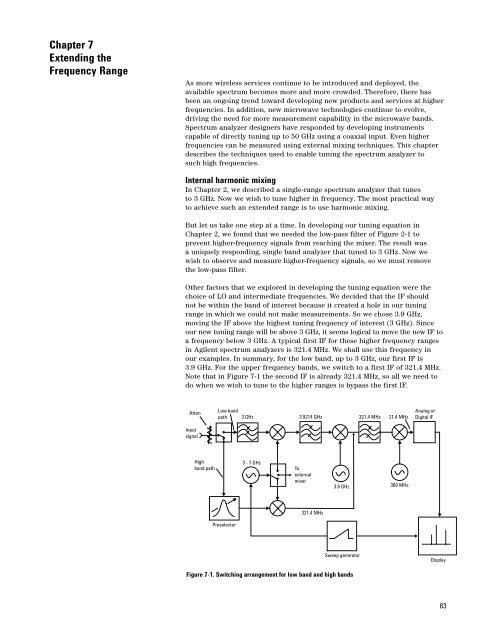
our examples. In summary, for the low band, up to 3 GHz, our first IF is<br />
3.9 GHz. For the upper frequency bands, we switch to a first IF of 321.4 MHz.<br />
Note that in Figure 7-1 the second IF is already 321.4 MHz, so all we need to<br />
do when we wish to tune to the higher ranges is bypass the first IF.<br />
Atten<br />
Low band<br />
path<br />
3 GHz<br />
3.9214 GHz<br />
321.4 MHz 21.4 MHz<br />
Analog or<br />
Digital IF<br />
Input<br />
signal<br />
High<br />
band path<br />
3 - 7 GHz<br />
To<br />
external<br />
mixer<br />
3.6 GHz<br />
300 MHz<br />
321.4 MHz<br />
Preselector<br />
Sweep generator<br />
Display<br />
Figure 7-1. Switching arrangement for low band and high bands<br />
83


