

Agilent Spectrum Analysis Basics - Agilent Technologies
Agilent Spectrum Analysis Basics - Agilent Technologies
Agilent Spectrum Analysis Basics - Agilent Technologies

Create successful ePaper yourself
Turn your PDF publications into a flip-book with our unique Google optimized e-Paper software.
2D dB 3D dB<br />
3D dB 3D dB<br />
With a constant LO level, the mixer output is linearly related to the input<br />
signal level. For all practical purposes, this is true as long as the input signal<br />
is more than 15 to 20 dB below the level of the LO. There are also terms<br />
involving harmonics of the input signal:<br />
(3k 3 /4)V LO V 1 2 sin(ω LO – 2 ω 1 )t,<br />
(k 4 /8)V LO V 1 3 sin(ω LO – 3ω 1 )t, etc.<br />
These terms tell us that dynamic range due to internal distortion is a<br />
function of the input signal level at the input mixer. Let’s see how this works,<br />
using as our definition of dynamic range, the difference in dB between the<br />
fundamental tone and the internally generated distortion.<br />
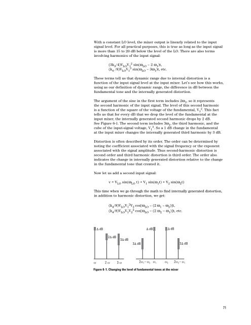
The argument of the sine in the first term includes 2ω 1 , so it represents<br />
the second harmonic of the input signal. The level of this second harmonic<br />
is a function of the square of the voltage of the fundamental, V 1 2 . This fact<br />
tells us that for every dB that we drop the level of the fundamental at the<br />
input mixer, the internally generated second harmonic drops by 2 dB.<br />
See Figure 6-1. The second term includes 3ω 1 , the third harmonic, and the<br />
cube of the input-signal voltage, V 1 3 . So a 1 dB change in the fundamental<br />
at the input mixer changes the internally generated third harmonic by 3 dB.<br />
Distortion is often described by its order. The order can be determined by<br />
noting the coefficient associated with the signal frequency or the exponent<br />
associated with the signal amplitude. Thus second-harmonic distortion is<br />
second order and third harmonic distortion is third order. The order also<br />
indicates the change in internally generated distortion relative to the change<br />
in the fundamental tone that created it.<br />
Now let us add a second input signal:<br />
v = V LO sin(ω LO t) + V 1 sin(ω 1 t) + V 2 sin(ω 2 t)<br />
This time when we go through the math to find internally generated distortion,<br />
in addition to harmonic distortion, we get:<br />
(k 4 /8)V LO V 1 2 V 2 cos[ω LO – (2 ω 1 – ω 2 )]t,<br />
(k 4 /8)V LO V 1 V 2<br />
2 cos[ω LO – (2 ω 2 – ω 1 )]t, etc.<br />
D dB<br />
D dB<br />
D dB<br />
w 2 w 3 w 2w 1<br />
– w 2<br />
w 1<br />
w 2<br />
2w 2<br />
– w 1<br />
Figure 6-1. Changing the level of fundamental tones at the mixer<br />
71


