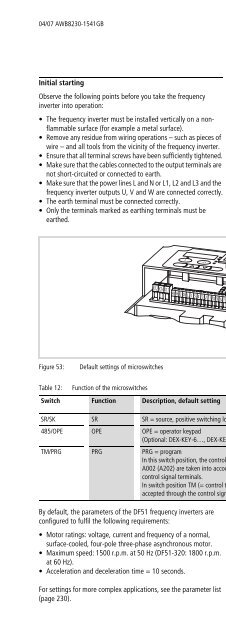
Frequency Inverter DF51... - Moeller.com.tr
Frequency Inverter DF51... - Moeller.com.tr
Frequency Inverter DF51... - Moeller.com.tr
- No tags were found...

Create successful ePaper yourself
Turn your PDF publications into a flip-book with our unique Google optimized e-Paper software.
Setting parameters04/07 AWB8230-1541GBActual value and status signalsThis section describes how to assign various actual values andstatus signals to the con<strong>tr</strong>ol signal terminals.Con<strong>tr</strong>ol signal terminal overview (output)The table below provides an overview of the output con<strong>tr</strong>ol signalterminals and a brief description of the functions which you canassign to the analog and digital outputs. The following pagescontain a detailed description of each function.Table 29:DesignationBrief description of the functionsValue 1) Designation DescriptionAnalog outputsAM – Analog output,measured valueindication selectionThrough this output, the frequency can be issued through a connected analog or digitalmeasurement device. Alternatively, the motor current can be output (PNU C028).0 to +10 V HLoad carrying capacity: 1 mAL – 0 V Reference potential for the following con<strong>tr</strong>ol signal terminals• Analog inputs O and OI• Analog output AM• Reference voltage +10 V (H)• Con<strong>tr</strong>ol voltage +24 V (P24)Digital outputs 11 and 12Parameterizing PNU C021 and C022RUN 00 RUN signal The RUN signal is output during operation of the motor.FA1 01 Reference frequencyreachedf reff 2f 1FA1FA2f s = reference frequencyFA2 02 <s<strong>tr</strong>ong>Frequency</s<strong>tr</strong>ong> signal If a digital output is configured as FA1, a signal is issued as long as the reference value is reached.If a digital signal is configured as FA2, a signal is output as long as the frequencies defined underPNU C042 (during acceleration ramp) and PNU C043 (during deceleration ramp) are exceeded.OL 03 Overload warning The OL (overload) signal is output when the overload alarm threshold (adjustable underPNU C041) is exceeded.OD 04 PID con<strong>tr</strong>ol deviation The OD (Output Deviation) signal is issued when the PID con<strong>tr</strong>ol deviation set with PNU C044 isexceeded.AL 05 Fault/alarm signal The AL (alarm) signal is issued when a fault occurs.Dc 06 Warning: Analogreference value signalinterruptedFBV 07 Warning: Actual valuesignal to PID con<strong>tr</strong>ollerinterruptedNDc 08 Fault/Warning: Faulty<s<strong>tr</strong>ong>com</s<strong>tr</strong>ong>munication throughserial interface.LOG 09 Result of logic link(PNU C143)1) To activate the function, enter this value in the corresponding parameter.2) This output can be used as both a signal output and a normal digital output.Dc (Disconnect Detect) monitors the analog inputs in RUN mode and signals any failure or dropoffbelow the reference value signal.• Input O (0 to 10 V) below value in PNU b082 or• current signal at input OI less than 4 mA.FBV (Feedback Value Check) monitors the PV feedback signal from the PID con<strong>tr</strong>oller in RUNmode.Reference/actual value differential of PID con<strong>tr</strong>ol exceeds the tolerance range in PNU C052/C053.NDc (Network Detection Signal) monitors the watchdog timer during <s<strong>tr</strong>ong>com</s<strong>tr</strong>ong>munication through theRS 485 serial interface (Modbus). Fault/warning dependent on PNU C077 – <s<strong>tr</strong>ong>com</s<strong>tr</strong>ong>municationwatchdog timer has expired: <s<strong>tr</strong>ong>com</s<strong>tr</strong>ong>munications are faulty.LOG (Logical Output) shows the result of PNU C143 (High, Low) of the logic function (AND, OR,XOR).104