Frequency Inverter DF51... - Moeller.com.tr
Frequency Inverter DF51... - Moeller.com.tr
Frequency Inverter DF51... - Moeller.com.tr
- No tags were found...

Create successful ePaper yourself
Turn your PDF publications into a flip-book with our unique Google optimized e-Paper software.
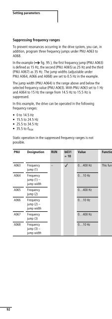
Error messages04/07 AWB8230-1541GBTroubleshootingFault Condition Possible cause RemedyThe motor does notstart.The motor turns inthe wrong direction.The motor will notstart.The motor does notoperate smoothly.There is no voltagepresent at outputs U,V and W.There is voltagepresent at outputs U,V and W.Is voltage applied to terminals L, N and/or L1, L2and L3? If yes, is the ON lamp lit?Is the LED display on the keypad displaying a faultmessage (E…)?Has a start signal been issued?Has a reference frequency been entered underPNU F001 (for con<strong>tr</strong>ol through operator panelonly)?Is the reference input through the potentiometercorrectly wired to terminals H, O and L?Are inputs O and OI connected correctly forexternal reference input?Are the digital inputs configured as RST or FRSstill active?Has the correct source for the reference frequency(PNU A001) been set?Has the correct source for the start signal(PNU A002) been set?Is the motor blocked or is the motor load toohigh?– Are output terminals U, V and W correctlyconnected? Does the connection of terminals U, Vand W correspond with the direction of rotationof the motor?Are the con<strong>tr</strong>ol signal terminals correctly wired?Has PNU F004 been correctly configured?Check terminals L1, L2, L3 and U, V, W. Switchon the supply voltage.Analyze the cause of the fault message(a section “Fault signals”, page 181).Acknowledge the fault message with the reset<s<strong>tr</strong>ong>com</s<strong>tr</strong>ong>mand (for example by pressing the Stop key).Issue the start signal with the Start key orthrough the FWD/REV input.Enter a reference frequency under PNU F001.Check that the potentiometer is connectedcorrectly.Check that the reference signal is correctlyconnected.Deactivate RST and/or FRS.Check the signal on digital input 5 (defaultsetting: RST).Correct PNU A001 accordingly.Correct PNU A002 accordingly.Reduce the load acting on the motor. Test themotor without load.Connect output terminals U, V and W correctly tothe motor according to the required direction ofmotor rotation (generally the sequence U, V, Wcauses clockwise operation).Con<strong>tr</strong>ol signal terminal FW(D) for clockwiseoperation and REV for anticlockwise operation.Set the desired direction of rotation underPNU F04.– No reference value is applied to terminal O or OI. Check the potentiometer or the externalreference value generator and replace ifnecessary.Is a fixed frequency accessed?Is the motor load too high?Observe the sequence of priority: the fixedfrequencies always have priority over inputs Oand OI.Reduce the motor load as the overload limit willprevent the motor reaching its normal speed ifthere is an overload.– Are the load changes on the motor too high? Select a frequency inverter and motor with ahigher performance.Reduce the level of load changes.Do resonant frequencies occur on the motor?Mask these frequencies with the frequency jumps(PNU A063 to A068) or change the pulsefrequency (PNU b083).186