Temperature Controller - Staveb AG
Temperature Controller - Staveb AG
Temperature Controller - Staveb AG
- No tags were found...

You also want an ePaper? Increase the reach of your titles
YUMPU automatically turns print PDFs into web optimized ePapers that Google loves.
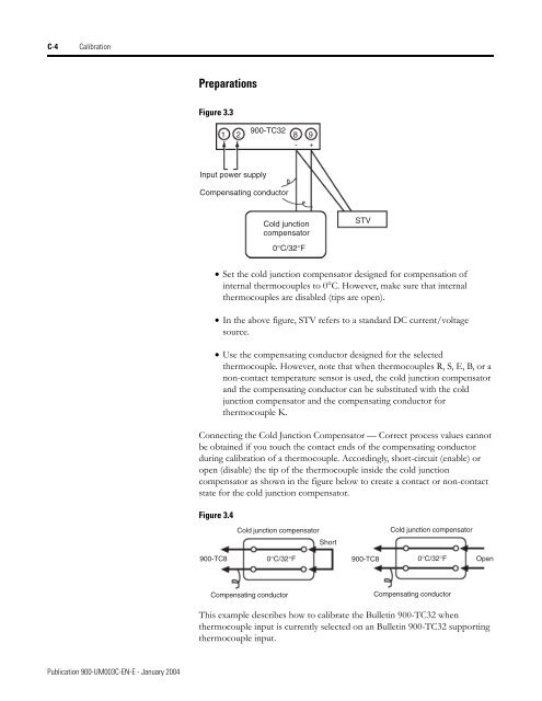
C-4 CalibrationPreparationsFigure 3.31 2900-TC328 9- +Input power supplyCompensating conductorCold junctioncompensatorSTV0°C/32°F• Set the cold junction compensator designed for compensation ofinternal thermocouples to 0°C. However, make sure that internalthermocouples are disabled (tips are open).• In the above figure, STV refers to a standard DC current/voltagesource.• Use the compensating conductor designed for the selectedthermocouple. However, note that when thermocouples R, S, E, B, or anon-contact temperature sensor is used, the cold junction compensatorand the compensating conductor can be substituted with the coldjunction compensator and the compensating conductor forthermocouple K.Connecting the Cold Junction Compensator — Correct process values cannotbe obtained if you touch the contact ends of the compensating conductorduring calibration of a thermocouple. Accordingly, short-circuit (enable) oropen (disable) the tip of the thermocouple inside the cold junctioncompensator as shown in the figure below to create a contact or non-contactstate for the cold junction compensator.Figure 3.4Cold junction compensatorCold junction compensatorShort900-TC80°C/32°F900-TC80°C/32°FOpenCompensating conductorCompensating conductorThis example describes how to calibrate the Bulletin 900-TC32 whenthermocouple input is currently selected on an Bulletin 900-TC32 supportingthermocouple input.Publication 900-UM003C-EN-E - January 2004