Temperature Controller - Staveb AG
Temperature Controller - Staveb AG
Temperature Controller - Staveb AG
- No tags were found...

You also want an ePaper? Increase the reach of your titles
YUMPU automatically turns print PDFs into web optimized ePapers that Google loves.
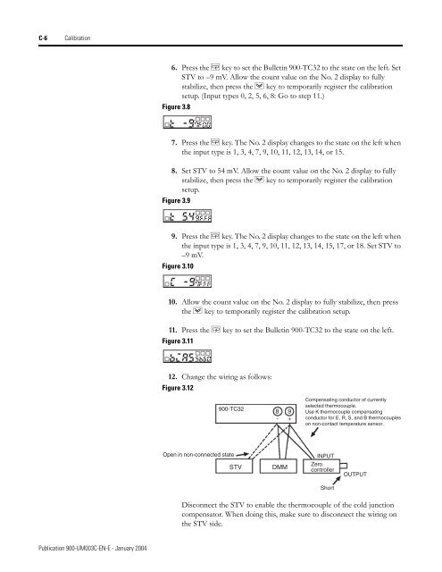
C-6 Calibration6. Press the M key to set the Bulletin 900-TC32 to the state on the left. SetSTV to –9 mV. Allow the count value on the No. 2 display to fullystabilize, then press the D key to temporarily register the calibrationsetup. (Input types 0, 2, 5, 6, 8: Go to step 11.)Figure 3.87. Press the M key. The No. 2 display changes to the state on the left whenthe input type is 1, 3, 4, 7, 9, 10, 11, 12, 13, 14, or 15.8. Set STV to 54 mV. Allow the count value on the No. 2 display to fullystabilize, then press the D key to temporarily register the calibrationsetup.Figure 3.99. Press the M key. The No. 2 display changes to the state on the left whenthe input type is 1, 3, 4, 7, 9, 10, 11, 12, 13, 14, 15, 17, or 18. Set STV to–9 mV.Figure 3.1010. Allow the count value on the No. 2 display to fully stabilize, then pressthe D key to temporarily register the calibration setup.11. Press the M key to set the Bulletin 900-TC32 to the state on the left.Figure 3.1112. Change the wiring as follows:Figure 3.12900-TC328 9- +Compensating conductor of currentlyselected thermocouple.Use K thermocouple compensatingconductor for E, R, S, and B thermocoupleson non-contact temperature sensor.Open in non-connected stateINPUTSTVDMMZerocontrollerOUTPUTShortDisconnect the STV to enable the thermocouple of the cold junctioncompensator. When doing this, make sure to disconnect the wiring onthe STV side.Publication 900-UM003C-EN-E - January 2004