- Page 7 and 8: Table of Contentstoc-iiiExecuting t
- Page 9 and 10: Table of Contentstoc-vMemory Error
- Page 11 and 12: PrefaceSafety PrecautionsSafety Sig
- Page 13 and 14: Chapter 1Bulletin 900-TC32 Input an
- Page 15 and 16: Bulletin 900-TC32 Input and Output
- Page 17 and 18: Bulletin 900-TC32 Input and Output
- Page 19 and 20: Chapter 2PreparationsHardware Insta
- Page 21 and 22: Preparations 2-3System Wiring and I
- Page 23 and 24: Preparations 2-5ATTENTION!• Clean
- Page 25 and 26: Preparations 2-7Removing and Attach
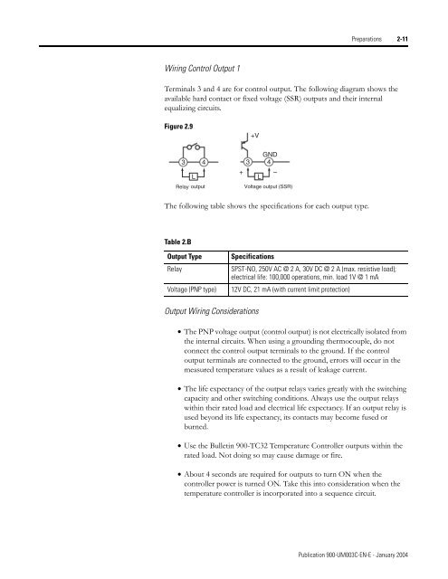
- Page 27: Preparations 2-9• Separate input
- Page 31 and 32: Preparations 2-13Figure 2.12 Commun
- Page 33 and 34: Chapter 3Configuration and Basic Op
- Page 35 and 36: Configuration and Basic Operation 3
- Page 37 and 38: Configuration and Basic Operation 3
- Page 39 and 40: Configuration and Basic Operation 3
- Page 41 and 42: Configuration and Basic Operation 3
- Page 43 and 44: Configuration and Basic Operation 3
- Page 45 and 46: Configuration and Basic Operation 3
- Page 47 and 48: Configuration and Basic Operation 3
- Page 49 and 50: Configuration and Basic Operation 3
- Page 51 and 52: Configuration and Basic Operation 3
- Page 53 and 54: Configuration and Basic Operation 3
- Page 55 and 56: Configuration and Basic Operation 3
- Page 57 and 58: Configuration and Basic Operation 3
- Page 59 and 60: Configuration and Basic Operation 3
- Page 61 and 62: Chapter 4Parameter Adjustments and
- Page 63 and 64: Parameter Adjustments and Applicati
- Page 65 and 66: Parameter Adjustments and Applicati
- Page 67 and 68: Parameter Adjustments and Applicati
- Page 69 and 70: Parameter Adjustments and Applicati
- Page 71 and 72: Parameter Adjustments and Applicati
- Page 73 and 74: Parameter Adjustments and Applicati
- Page 75 and 76: Parameter Adjustments and Applicati
- Page 77 and 78: Parameter Adjustments and Applicati
- Page 79 and 80:
Parameter Adjustments and Applicati
- Page 81 and 82:
Parameter Adjustments and Applicati
- Page 83 and 84:
Parameter Adjustments and Applicati
- Page 85 and 86:
Chapter 5Parameter Functions and De
- Page 87 and 88:
Parameter Functions and Definitions
- Page 89 and 90:
Parameter Functions and Definitions
- Page 91 and 92:
Parameter Functions and Definitions
- Page 93 and 94:
Parameter Functions and Definitions
- Page 95 and 96:
Parameter Functions and Definitions
- Page 97 and 98:
Parameter Functions and Definitions
- Page 99 and 100:
Parameter Functions and Definitions
- Page 101 and 102:
Parameter Functions and Definitions
- Page 103 and 104:
Parameter Functions and Definitions
- Page 105 and 106:
Parameter Functions and Definitions
- Page 107 and 108:
Parameter Functions and Definitions
- Page 109 and 110:
Parameter Functions and Definitions
- Page 111 and 112:
Parameter Functions and Definitions
- Page 113 and 114:
Parameter Functions and Definitions
- Page 115 and 116:
Parameter Functions and Definitions
- Page 117 and 118:
Parameter Functions and Definitions
- Page 119 and 120:
Parameter Functions and Definitions
- Page 121 and 122:
Parameter Functions and Definitions
- Page 123 and 124:
Parameter Functions and Definitions
- Page 125 and 126:
Parameter Functions and Definitions
- Page 127 and 128:
Chapter 6Troubleshooting and Error
- Page 129 and 130:
Troubleshooting and Error Indicatio
- Page 131 and 132:
Appendix ASpecificationsFor the set
- Page 133 and 134:
A-3Sensor Input SettingRangesTable
- Page 135 and 136:
Appendix BParameter Operations List
- Page 137 and 138:
B-3Table B.C Initial Setting Functi
- Page 139 and 140:
B-5Figure B.1Power ONOperationfunct
- Page 141 and 142:
B-7Advanced setting function groupP
- Page 143 and 144:
Appendix CCalibrationParameter Stru
- Page 145 and 146:
Calibration C-3User CalibrationCali
- Page 147 and 148:
Calibration C-51. Connect the power
- Page 149 and 150:
Calibration C-713. Allow the count
- Page 151 and 152:
Calibration C-91. Connect the power
- Page 153 and 154:
Calibration C-11Platinum Resistance
- Page 155 and 156:
Appendix DGlossaryAdaptive Tuning:
- Page 157 and 158:
Glossary D-3Deviation: A departure
- Page 159 and 160:
Glossary D-5Loop Break Alarm: This
- Page 161 and 162:
Glossary D-7Serial Communications:
- Page 164 and 165:
Back Coverwww.rockwellautomation.co