

Hardware and Engineering DF6-340-... Frequency ... - Moeller.com.tr
Hardware and Engineering DF6-340-... Frequency ... - Moeller.com.tr
Hardware and Engineering DF6-340-... Frequency ... - Moeller.com.tr

Create successful ePaper yourself
Turn your PDF publications into a flip-book with our unique Google optimized e-Paper software.
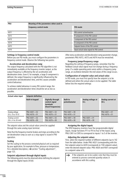
Setting Parameters01/02 AWB8230-1413GBPNUMeaning of the parameters when used infrequency con<strong>tr</strong>ol modePID modeA071 – PID con<strong>tr</strong>ol active/inactiveA072P <s<strong>tr</strong>ong>com</s<strong>tr</strong>ong>ponent of the PID con<strong>tr</strong>olA073I <s<strong>tr</strong>ong>com</s<strong>tr</strong>ong>ponent of the PID con<strong>tr</strong>olA074D <s<strong>tr</strong>ong>com</s<strong>tr</strong>ong>ponent of the PID con<strong>tr</strong>olA075Setpoint factor of the PID con<strong>tr</strong>olA076Input actual value signal for PID con<strong>tr</strong>olSettings in frequency con<strong>tr</strong>ol modeBefore you use PID mode, you must configure the parameters infrequency con<strong>tr</strong>ol mode. Observe the following two points:Acceleration <s<strong>tr</strong>ong>and</s<strong>tr</strong>ong> deceleration rampThe output frequency calculated with the PID algorithm is notimmediately available at the frequency inverter output, as theoutput frequency is affected by the set acceleration <s<strong>tr</strong>ong>and</s<strong>tr</strong>ong>deceleration times. Even if, for example, a large D <s<strong>tr</strong>ong>com</s<strong>tr</strong>ong>ponent isdefined, the output frequency is significantly influenced by theacceleration <s<strong>tr</strong>ong>and</s<strong>tr</strong>ong> deceleration time, <s<strong>tr</strong>ong>and</s<strong>tr</strong>ong> this causes unstablecon<strong>tr</strong>ol behaviour.To achieve stable behaviour in every PID con<strong>tr</strong>ol range, theacceleration <s<strong>tr</strong>ong>and</s<strong>tr</strong>ong> deceleration times should be set as low aspossible.After every acceleration <s<strong>tr</strong>ong>and</s<strong>tr</strong>ong> deceleration ramp parameter change,parameters PNU A072, A073 <s<strong>tr</strong>ong>and</s<strong>tr</strong>ong> A074 must be rematched.<s<strong>tr</strong>ong>Frequency</s<strong>tr</strong>ong> jumps/frequency rangeRegarding the setting of frequency jumps, remember that thefeedback actual value signal must not change during a frequencyjump. If a stable operating point exists within a frequency jumprange, an oscillation between the end values of this range occurs.Configuration of setpoint value <s<strong>tr</strong>ong>and</s<strong>tr</strong>ong> actual valueIn PID mode, you must first specify how the setpoint is to bedefined <s<strong>tr</strong>ong>and</s<strong>tr</strong>ong> where the actual value is to be supplied. The tablebelow lists the required settings:Actual value inputSetpoint definitionBuilt-in keypadDigitally throughcon<strong>tr</strong>ol signalterminals(fixed frequencies)Built-inpotentiometerAnalog voltage atO-LAnalog current atOI-LAnalog voltage(O-L: 0 to 10 V)Analog current(OI-L: 4 to 20 mA)PNU A001 = 02PNU A076 = 01PNU A001 = 02PNU A076 = 01PNU A001 = 00PNU A076 = 01– PNU A001 = 01PNU A076 = 01PNU A001 = 02PNU A076 = 00PNU A001 = 02PNU A076 = 00PNU A001 = 00PNU A076 = 00PNU A001 = 01PNU A076 = 00–The setpoint value <s<strong>tr</strong>ong>and</s<strong>tr</strong>ong> the actual value cannot be suppliedthrough the same analog input terminal.Note that the frequency inverter brakes <s<strong>tr</strong>ong>and</s<strong>tr</strong>ong> stops according to theset deceleration ramp as soon as a stop signal is issued in PIDoperation.ScalingSet the scaling to the process-corrected physical unit as requiredby your application, for example to flow, pressure or temperature.For a detailed description, a section “Scaling adjustment”,page 123.Setpoint adjustment through digital inputsThe following points must be observed when defining the setpointthrough the digital inputs (4-bit):Assigning the digital inputsThe <s<strong>tr</strong>ong>DF6</s<strong>tr</strong>ong> frequency inverters have five programmable digitalinputs. Assign functions FF1 to FF4 to four of the inputs usingPNU C001 to C005 to correspond to inputs 1 to 5 of the inverter.Adjusting the setpoint valuesFirst, select the required number of different setpoints (up to 16)from the table below. Under PNU A021 (corresponding with thefirst setpoint value) to A035 (corresponds to 15th setpoint value),enter the desired setpoint value. PNU A020 <s<strong>tr</strong>ong>and</s<strong>tr</strong>ong> F001 correspondto a setpoint value of 0.hIf the setpoints are to be scaled, note that they must beentered as process-corrected quantity values inaccordance with this scaling.124


