

Hardware and Engineering DF6-340-... Frequency ... - Moeller.com.tr
Hardware and Engineering DF6-340-... Frequency ... - Moeller.com.tr
Hardware and Engineering DF6-340-... Frequency ... - Moeller.com.tr

You also want an ePaper? Increase the reach of your titles
YUMPU automatically turns print PDFs into web optimized ePapers that Google loves.
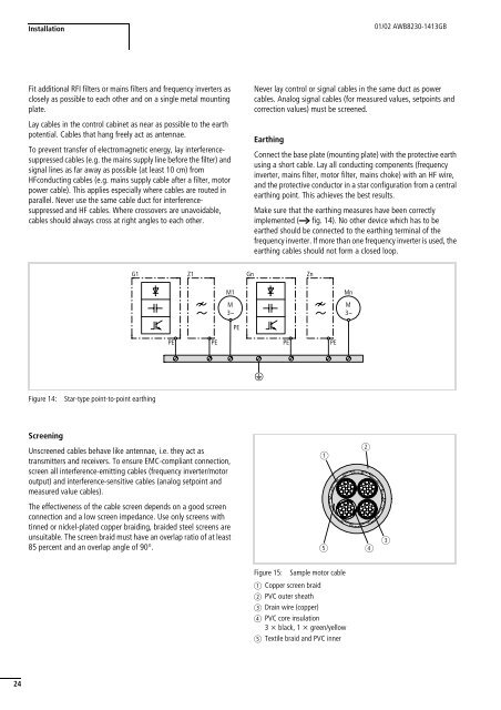
Installation01/02 AWB8230-1413GBFit additional RFI filters or mains filters <s<strong>tr</strong>ong>and</s<strong>tr</strong>ong> frequency inverters asclosely as possible to each other <s<strong>tr</strong>ong>and</s<strong>tr</strong>ong> on a single metal mountingplate.Lay cables in the con<strong>tr</strong>ol cabinet as near as possible to the earthpotential. Cables that hang freely act as antennae.To prevent <strong>tr</strong>ansfer of elec<strong>tr</strong>omagnetic energy, lay interferencesuppressedcables (e.g. the mains supply line before the filter) <s<strong>tr</strong>ong>and</s<strong>tr</strong>ong>signal lines as far away as possible (at least 10 cm) fromHFconducting cables (e.g. mains supply cable after a filter, motorpower cable). This applies especially where cables are routed inparallel. Never use the same cable duct for interferencesuppressed<s<strong>tr</strong>ong>and</s<strong>tr</strong>ong> HF cables. Where crossovers are unavoidable,cables should always cross at right angles to each other.Never lay con<strong>tr</strong>ol or signal cables in the same duct as powercables. Analog signal cables (for measured values, setpoints <s<strong>tr</strong>ong>and</s<strong>tr</strong>ong>correction values) must be screened.EarthingConnect the base plate (mounting plate) with the protective earthusing a short cable. Lay all conducting <s<strong>tr</strong>ong>com</s<strong>tr</strong>ong>ponents (frequencyinverter, mains filter, motor filter, mains choke) with an HF wire,<s<strong>tr</strong>ong>and</s<strong>tr</strong>ong> the protective conductor in a star configuration from a cen<strong>tr</strong>alearthing point. This achieves the best results.Make sure that the earthing measures have been correctlyimplemented (a fig. 14). No other device which has to beearthed should be connected to the earthing terminal of thefrequency inverter. If more than one frequency inverter is used, theearthing cables should not form a closed loop.G1 Z1Gn ZnM1M3hMnM3hPEPEPEPEPEeFigure 14:Star-type point-to-point earthingScreeningUnscreened cables behave like antennae, i.e. they act as<strong>tr</strong>ansmitters <s<strong>tr</strong>ong>and</s<strong>tr</strong>ong> receivers. To ensure EMC-<s<strong>tr</strong>ong>com</s<strong>tr</strong>ong>pliant connection,screen all interference-emitting cables (frequency inverter/motoroutput) <s<strong>tr</strong>ong>and</s<strong>tr</strong>ong> interference-sensitive cables (analog setpoint <s<strong>tr</strong>ong>and</s<strong>tr</strong>ong>measured value cables).The effectiveness of the cable screen depends on a good screenconnection <s<strong>tr</strong>ong>and</s<strong>tr</strong>ong> a low screen impedance. Use only screens withtinned or nickel-plated copper braiding, braided steel screens areunsuitable. The screen braid must have an overlap ratio of at least85 percent <s<strong>tr</strong>ong>and</s<strong>tr</strong>ong> an overlap angle of 90°.abe d cFigure 15: Sample motor cablea Copper screen braidb PVC outer sheathc Drain wire (copper)d PVC core insulation3 x black, 1 x green/yellowe Textile braid <s<strong>tr</strong>ong>and</s<strong>tr</strong>ong> PVC inner24


