

Hardware and Engineering DF6-340-... Frequency ... - Moeller.com.tr
Hardware and Engineering DF6-340-... Frequency ... - Moeller.com.tr
Hardware and Engineering DF6-340-... Frequency ... - Moeller.com.tr

You also want an ePaper? Increase the reach of your titles
YUMPU automatically turns print PDFs into web optimized ePapers that Google loves.
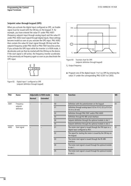
Programming the Con<strong>tr</strong>olSignal Terminals01/02 AWB8230-1413GBSetpoint value through keypad (OPE)When you activate the digital input configured as OPE, an Enablesignal must be issued with the ON key on the keypad. If, forexample, you have entered the value 01 under PNU A001(frequency setpoint input through analog input) <s<strong>tr</strong>ong>and</s<strong>tr</strong>ong> the value 01under PNU A002 (start signal through digital input), these settingsbe<s<strong>tr</strong>ong>com</s<strong>tr</strong>ong>e invalid as soon as you activate the OPE input. PNU A002then contain the value 02 (start signal through ON key) <s<strong>tr</strong>ong>and</s<strong>tr</strong>ong> thesetpoint frequency under PNU A020 or PNU F001 be<s<strong>tr</strong>ong>com</s<strong>tr</strong>ong>es active.If you activate the OPE input while the inverter is in RUN mode, itdecelerates <s<strong>tr</strong>ong>and</s<strong>tr</strong>ong> can then be started with the ON key on the device.If the start signal is still active, the frequency inverter acceleratesto the previously set frequency again as soon as you deactivate theOPE input.OPE1FWDFWP24FWOPEf oPNU A020/F001Figure 83: Function chart for OPE(setpoint definition through keypad)f o : Output frequencyX Program one of the digital inputs 1 to 5 as OPE by entering thevalue 31 under the corresponding PNU (C001 to C005).Figure 82:Digital input 1 configured as OPE(setpoint definition through keypad)PNU Name Adjustable in RUN mode Value Function WEA001<s<strong>tr</strong>ong>Frequency</s<strong>tr</strong>ong>setpointdefinitionNormalExtended– – 00 Definition with the potentiometer on the keypad 0101 Definition through analog input O (0 to 10 V), O2 (g10 V) orOI (4 to 20 mA)02 Definition through PNU F001 <s<strong>tr</strong>ong>and</s<strong>tr</strong>ong>/or PNU A02003 Definition through RS 485 serial interface04 Setpoint definition through the optional module in slot 105 Setpoint definition through the optional module in slot 2A002 Start signal – – 01 The motor start signal is issued through the FW input or adigital input configured as REV.02 The signal for starting the motor is issued by the ON key onthe keypad.03 The motor start signal is issued through the RS 485interface.04 The motor start signal is issued through the optional modulein slot 1.05 The motor start signal is issued through the optional modulein slot 2.0190


