

Hardware and Engineering DF6-340-... Frequency ... - Moeller.com.tr
Hardware and Engineering DF6-340-... Frequency ... - Moeller.com.tr
Hardware and Engineering DF6-340-... Frequency ... - Moeller.com.tr

Create successful ePaper yourself
Turn your PDF publications into a flip-book with our unique Google optimized e-Paper software.
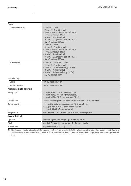
<s<strong>tr</strong>ong>Engineering</s<strong>tr</strong>ong>01/02 AWB8230-1413GBRelaysChangeover contactsMake contactsInternal voltagesCon<strong>tr</strong>olSetpoint definitionAnalog <s<strong>tr</strong>ong>and</s<strong>tr</strong>ong> digital actuationAnalog inputsDigital inputsAnalog outputs• Contacts K11-K14– 250 V AC, 2 A (resistive load)– 250 V AC, 0.2 A (inductive load, p.f. = 0.4)– 100 V AC, minimum 10 mA– 30VDC, 8A (resistive load)– 30 V DC, 0.6 A (inductive load, p.f. = 0.4)– 5 V DC, minimum 100 mA• Contacts K11-K12– 250 V AC, 1 A (resistive load)– 250 V AC, 0.2 A (inductive load, p.f. = 0.4)– 100 V AC, minimum 10 mA– 30 V DC, 1 A (resistive load)– 30 V DC, 0.2 A (inductive load, p.f. = 0.4)– 5 V DC, minimum 100 mA• Contacts K23-K24 <s<strong>tr</strong>ong>and</s<strong>tr</strong>ong> K33-K34– 250 V AC, 5 A (resistive load)– 250 V AC, 1 A (inductive load, p.f. = 0.4)– 30 V DC, 5 A (resistive load)– 30 V DC, 1 A (inductive load, p.f. = 0.4)– 5 V DC, minimum 1 mA24 V DC, maximum 30 mA10 V DC, maximum 10 mA• 1 input, 0 to 10 V, input impedance 10 kO• 1 input, 4 to 20 mA, load impedance 250 O• 1 input, +10 to –10 V, input impedance 10 kO5 inputs, user-configurable <s<strong>tr</strong>ong>and</s<strong>tr</strong>ong> one input for “start/stop clockwise operation”• 1 output for motor frequency or current, 10 V, up to 1.2 mA• 1 output, 0 to 10 V, up to 2 mA, user-configurable• 1 output, 4 to 20 mA, user-configurableOne changeover contact <s<strong>tr</strong>ong>and</s<strong>tr</strong>ong> two make contacts, user-configurableRelay outputsKeypad (built-in)Operation6 function keys for con<strong>tr</strong>olling <s<strong>tr</strong>ong>and</s<strong>tr</strong>ong> parameterizing the <s<strong>tr</strong>ong>DF6</s<strong>tr</strong>ong>DisplayFour-digit, 7-segment display <s<strong>tr</strong>ong>and</s<strong>tr</strong>ong> ten LEDs (for status signals)Potentiometer Setpoint definition (0 to 270°)1) If the frequency inverter is to be installed in a con<strong>tr</strong>ol panel, enclosure or similar installation, the temperature within the enclosure or con<strong>tr</strong>ol panel isconsidered to be ambient temperature T a . The use of fans should be considered to ensure that the ambient temperature remains within permissiblelimits.14


