- Page 1 and 2:
Protectionand controlSepam rangeSep
- Page 3 and 4:
ContentsMetering functionschapter /
- Page 5 and 6:
Maximum demand phase currentsOperat
- Page 7 and 8:
Residual currentOperationThis opera
- Page 9 and 10:
FrequencyOperationThis function giv
- Page 11 and 12:
%32.521.510.5%0.10.050.0100 0.1000.
- Page 13 and 14:
Accumulated real/reactive energyOpe
- Page 15 and 16:
Residual voltageOperationThis funct
- Page 17 and 18:
Cumulative breaking current and num
- Page 19 and 20:
Differential current and through cu
- Page 21 and 22:
ContentsProtection functionschapter
- Page 23 and 24:
Commissioning, settingCheck:c the c
- Page 25 and 26:
Commissioning, settingCheck:c the c
- Page 27 and 28:
Measurement of phase shift with res
- Page 29 and 30:
Example of useWhen the current sens
- Page 31 and 32:
Commissioning, settingEarth fault c
- Page 33 and 34:
Directional earth faultANSI code 67
- Page 35 and 36:
Protection detection directionThe n
- Page 37 and 38:
Commissioning, settingEarth fault c
- Page 39 and 40:
Resistive earth faultANSI codefunct
- Page 41 and 42:
Thermal overloadANSI code 49functio
- Page 43 and 44:
Cold curvesI/Ib 1.00 1.05 1.10 1.15
- Page 45 and 46:
Cold curvesI/Ib 4.80 5.00 5.50 6.00
- Page 47 and 48:
Hot curvesI/Ib 1.00 1.05 1.10 1.15
- Page 49 and 50:
Commissioning, settingsCheck:c the
- Page 51 and 52:
CharacteristicscurvesettingIs set p
- Page 53 and 54:
Commissioning, settingsCheck:c the
- Page 55 and 56:
Block diagramk1>NstartF421/3I1I2I3I
- Page 57 and 58:
Phase undercurrentANSI code 37Block
- Page 59 and 60:
0,05IbIsF441/1F441/2F441/3F441/4F44
- Page 61 and 62:
CharacteristicsUs set pointsettinga
- Page 63 and 64:
Positive sequence undervoltageand p
- Page 65 and 66:
Neutral voltage displacementANSI co
- Page 67 and 68:
Rate of change of frequency protect
- Page 69 and 70:
c Low set point time delayFor good
- Page 71 and 72:
OverfrequencyANSI code 81function n
- Page 73 and 74:
Commissioning, settingCheck:c the c
- Page 75 and 76:
Commissioning, settingCheck:c the c
- Page 77 and 78:
Commissioning, settingCheck:c the c
- Page 79 and 80:
CharacteristicsdUs set pointrangere
- Page 81 and 82:
Percentage-based single-phase overc
- Page 83 and 84:
PerformanceThe performance of this
- Page 85 and 86:
Block diagramF621/1> 5,5 In&I1I1’
- Page 87 and 88:
Commissioning, settingNeutral curre
- Page 89 and 90:
AppendixContentschapter / pageappen
- Page 91 and 92:
Another practical method: the chart
- Page 93 and 94:
Very inverse time curve VIT or LTIt
- Page 95 and 96:
Ultra inverse time curve UITt (s)1
- Page 97 and 98:
General parameter settingsThe gener
- Page 99 and 100:
Protectionand controlSepam rangePro
- Page 101 and 102:
Control and monitoring functionsCon
- Page 103 and 104:
Open / close controlUseThis functio
- Page 105 and 106:
Special featuresc Input I15 (extern
- Page 107 and 108:
Special featuresc Input I15 (extern
- Page 109 and 110:
Special featuresc Input I15 (extern
- Page 111 and 112:
Special featuresc Input I15 (extern
- Page 113 and 114:
Special featuresc Input I15 (extern
- Page 115 and 116:
Open / close matching supervisionAp
- Page 117 and 118:
Block diagram: substation - busbar
- Page 119 and 120:
Operation counterphase fault trip c
- Page 121 and 122:
Load sheddingBlock diagramlogic inp
- Page 123 and 124:
IntertrippingBlock diagramprotectio
- Page 125 and 126:
ApplicationThis function provides r
- Page 127 and 128:
RecloserApplicationDesigned essenti
- Page 129 and 130:
IndicationsDisplay messagesList of
- Page 131 and 132:
De-excitationBlock diagramde-excita
- Page 133 and 134:
OperationA closing request made loc
- Page 135 and 136:
Disturbance recording triggeringBlo
- Page 137 and 138:
Open / close controlcapacitor bank
- Page 139 and 140:
Capacitor controlBlock diagraminten
- Page 141 and 142:
ApplicationThis function may be use
- Page 143 and 144:
Capacitor unbalanceBlock diagram"RE
- Page 145 and 146:
VT supervisionApplicationThis funct
- Page 147 and 148:
Remote control and remote annunciat
- Page 149 and 150:
Function set-up summary chart (cont
- Page 151 and 152:
Function set-up summary chart (cont
- Page 153 and 154:
Function set-up summary chart (cont
- Page 155 and 156:
Function set-up summary chart (cont
- Page 157 and 158:
InstallationContentschapter / pagei
- Page 159 and 160:
InstallationEquipment identificatio
- Page 161 and 162:
Optional accessoriesTSM 2001 pocket
- Page 163 and 164:
Sepam 2000 componentsslot 6 5 4 3 2
- Page 165 and 166:
CCA 660 or CCA 650connectorc Open t
- Page 167 and 168:
Accessories for CSPcurrent sensorsA
- Page 169 and 170:
Use of ACE 907 and AC 908c Connect
- Page 171 and 172:
InstallationUse and connection of s
- Page 173 and 174:
Connection of CSH 120 andCSH 200 co
- Page 175 and 176:
Connectionto CT with 1 A secondaryc
- Page 177 and 178:
Characteristicsc Accuracy:v amplitu
- Page 179 and 180:
Connection of 2 VTsThis arrangement
- Page 181 and 182:
InstallationConnection of Pt100 ter
- Page 183 and 184:
InstallationConnection of the Jbus/
- Page 185 and 186:
Use - commissioningDescription/useY
- Page 187 and 188: Use - commissioningDescription/use
- Page 189 and 190: Use - commissioningUse (current ope
- Page 191 and 192: Use - commissioningUse (current ope
- Page 193 and 194: Use - commissioningCommissioningChe
- Page 195 and 196: Use - commissioningCommissioning (c
- Page 197 and 198: Use - commissioningCommissioning (c
- Page 199 and 200: Use - commissioningCommissioning (c
- Page 201 and 202: Use - commissioningCommissioning (c
- Page 203 and 204: Use - commissioningCommissioning (c
- Page 205 and 206: Use - commissioningCommissioning (c
- Page 207 and 208: Use - commissioningCommissioning (c
- Page 209 and 210: Use - commissioningCommissioning (c
- Page 211 and 212: Use - commissioningCommissioning (c
- Page 213 and 214: Use - commissioningCommissioning (c
- Page 215 and 216: Use - commissioningCommissioning (c
- Page 217 and 218: Use - commissioningCommissioning (c
- Page 219 and 220: Use - commissioningCommissioning (c
- Page 221 and 222: Use - commissioningCommissioning (c
- Page 223 and 224: Use - commissioningCommissioning (c
- Page 225 and 226: Use - commissioningMaintenance (con
- Page 227 and 228: Use - commissioningSepam 2000 ident
- Page 229 and 230: Use - commissioningSepam 2000 ident
- Page 231 and 232: Use - commissioningPasswordUse of t
- Page 233 and 234: General characteristicsCharacterist
- Page 235 and 236: General characteristicsCharacterist
- Page 237: General characteristicsQualificatio
- Page 241 and 242: General characteristicsEffects of t
- Page 243 and 244: General characteristicsEffects of t
- Page 245 and 246: General characteristicsDependabilit
- Page 247 and 248: Appendix 1: reference documentsStan
- Page 249 and 250: Testing - setting record sheetsComm
- Page 251 and 252: Program logic parameters (customize
- Page 253 and 254: SETTING RECORD SHEETProject: ......
- Page 255 and 256: Sepam 2000 Substationfunction ident
- Page 257 and 258: Status menu parameters (cont’d)me
- Page 259 and 260: SETTING RECORD SHEETProject: ......
- Page 261 and 262: Sepam 2000 Transformerfunction iden
- Page 263 and 264: Status menu parameters (cont’d)me
- Page 265 and 266: SETTING RECORD SHEETProject: ......
- Page 267 and 268: Status menu parameters (cont’d)Se
- Page 269 and 270: SETTING RECORD SHEETProject: ......
- Page 271 and 272: Sepam 2000 Generatorfunction identi
- Page 273 and 274: Protectionand controlSepam rangeSep
- Page 275 and 276: InstallationEquipment identificatio
- Page 277 and 278: InstallationEquipment identificatio
- Page 279 and 280: InstallationEquipment identificatio
- Page 281 and 282: InstallationAssembly and wiring (co
- Page 283 and 284: InstallationConnection of current i
- Page 285 and 286: InstallationConnection of analog in
- Page 287 and 288: InstallationConnection of power sup
- Page 289 and 290:
Notes1/16 Installation - Use - Shee
- Page 291 and 292:
Use - commissioningDescription / us
- Page 293 and 294:
Use - commissioningDescription / us
- Page 295 and 296:
Use - commissioningUse (current ope
- Page 297 and 298:
Use - commissioningCommissioningChe
- Page 299 and 300:
Use - commissioningCommissioning (c
- Page 301 and 302:
Use - commissioningMaintenance (con
- Page 303 and 304:
2/14 Installation - Use - Sheets
- Page 305 and 306:
Notes2/16 Installation - Use - Shee
- Page 307 and 308:
Status menu parameters (cont’d)me
- Page 309 and 310:
Protectionand controlSepam rangeSep
- Page 311 and 312:
InstallationEquipment identificatio
- Page 313 and 314:
InstallationEquipment identificatio
- Page 315 and 316:
InstallationAssembly and wiring (co
- Page 317 and 318:
InstallationConnection of current i
- Page 319 and 320:
InstallationUse of the CSH 30 core
- Page 321 and 322:
InstallationConnection of the Jbus
- Page 323 and 324:
InstallationChecking prior to commi
- Page 325 and 326:
Use - commissioningDescription / us
- Page 327 and 328:
Use - commissioningDescription / us
- Page 329 and 330:
Use - commissioningUse (current ope
- Page 331 and 332:
Use - commissioningCommissioningChe
- Page 333 and 334:
Use - commissioningCommissioning (c
- Page 335 and 336:
Use - commissioningCommissioning (c
- Page 337 and 338:
Use - commissioningMaintenance (con
- Page 339 and 340:
Use - commissioningSepam 2000 ident
- Page 341 and 342:
2/18 Use - commissioning
- Page 343 and 344:
TestingGeneral informationProcedure
- Page 345 and 346:
TestingGeneral information (cont'd)
- Page 347 and 348:
TestingCabling testing by current i
- Page 349 and 350:
ITestingCabling testing by current
- Page 351 and 352:
ITestingCabling testing by current
- Page 353 and 354:
SETTING RECORD SHEETSite : ........
- Page 355 and 356:
TEST SHEET Sepam 2000Site : .......
- Page 357 and 358:
Protectionand controlSepam rangeSep
- Page 359 and 360:
InstallationUse conditionsInstallat
- Page 361 and 362:
InstallationEquipment identificatio
- Page 363 and 364:
InstallationAssembly and wiringDime
- Page 365 and 366:
InstallationUse and connection of c
- Page 367 and 368:
InstallationUse and connection of C
- Page 369 and 370:
InstallationConnection of power sup
- Page 371 and 372:
InstallationReplacement of Sepam 20
- Page 373 and 374:
Use - commissioningDescription / us
- Page 375 and 376:
Use - commissioningDescription / us
- Page 377 and 378:
Use - commissioningUse (current ope
- Page 379 and 380:
Use - commissioningCommissioningChe
- Page 381 and 382:
Use - commissioningCommissioning (c
- Page 383 and 384:
Use - commissioningCommissioning (c
- Page 385 and 386:
Use - commissioningCommissioning (c
- Page 387 and 388:
Use - commissioningCommissioning (c
- Page 389 and 390:
Use - commissioningMaintenance (con
- Page 391 and 392:
Use - commissioningPasswordThe user
- Page 393 and 394:
General characteristicsSepam 2000 l
- Page 395 and 396:
General characteristicsDependabilit
- Page 397 and 398:
Testingchapitre / pagetestinggenera
- Page 399 and 400:
Inhibition of outputsand test param
- Page 401 and 402:
Other diagram:This diagram may be u
- Page 403 and 404:
TestingCabling testing by current i
- Page 405 and 406:
TestingRestricted earth fault prote
- Page 407 and 408:
SETTING RECORD SHEETProject: ......
- Page 409 and 410:
TEST SHEET Sepam 2000Project: .....
- Page 411 and 412:
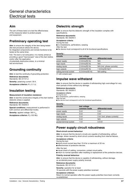
Electrical testsAimThe aim of these
- Page 413 and 414:
Testing of output effects in rated
- Page 415 and 416:
Effects of the environment on the e
- Page 417 and 418:
Appendix 1: reference documentsStan
- Page 419 and 420:
Contentspagepresentation 2connectio
- Page 421 and 422:
ImplementationSetting the communica
- Page 423 and 424:
Use of remote control bitsThe remot
- Page 425 and 426:
Events zoneThe events zone is a tab
- Page 427 and 428:
Test zoneThe test zone is a 16-word
- Page 429 and 430:
Measurements x 1 zoneThe measuremen
- Page 431 and 432:
Compact zoneThe compact zone contai
- Page 433 and 434:
Configuration zoneThe configuration
- Page 435 and 436:
Jbus data encoding (logical)Format
- Page 437 and 438:
I onA V/Hz W/ϕ Wh clear alarm rese
- Page 439 and 440:
Description of event codingAn event
- Page 441 and 442:
I onO offA V/Hz W/ϕ Wh clear alarm
- Page 443 and 444:
Sepam 2000 internal eventsThe inter
- Page 445 and 446:
switching of the setting terminal t
- Page 447 and 448:
Access to remote settings (cont’d
- Page 449 and 450:
Description of settingsData typeThe
- Page 451 and 452:
Reading of phase overcurrent protec
- Page 453 and 454:
If the master requests more exchang
- Page 455 and 456:
eading of block n° 79h of the reco
- Page 457 and 458:
Request framethis codeis used to se
- Page 459 and 460:
Reading of N words:function 3 or 4T
- Page 461 and 462:
Reading of diagnosiscounters: funct
- Page 463 and 464:
ExampleForcing of words 0800h to 08
- Page 465 and 466:
Protectionand controlSepam rangeSep
- Page 467 and 468:
Protection function testsContentANS
- Page 469 and 470:
Measurement and testing methodGener
- Page 471 and 472:
Checking of IDMT set point and time
- Page 473 and 474:
Voltage restrained overcurrent prot
- Page 475 and 476:
Earth fault protectionANSI code 50N
- Page 477 and 478:
Percentage-based single-phase overc
- Page 479 and 480:
c testing of TOnce the protection a
- Page 481 and 482:
examplec angle θo = 0° (see figur
- Page 483 and 484:
Checking of protection disengaging
- Page 485 and 486:
Setting Adjust = None does not take
- Page 487 and 488:
Cold curvesI/Ib 1.85 1.90 1.95 2.00
- Page 489 and 490:
Hot curves:t/T1 = f(OL, I/Ib)The fo
- Page 491 and 492:
Sensitive earth fault protectionANS
- Page 493 and 494:
Ii (% Ib) K10 99.9515 54.5020 35.44
- Page 495 and 496:
Testing of number of consecutive co
- Page 497 and 498:
Phase undercurrent protectionANSI c
- Page 499 and 500:
Remanent undervoltage protectionANS
- Page 501 and 502:
Phase-to-phase overvoltage protecti
- Page 503 and 504:
Testing by injection into input A1-
- Page 505 and 506:
Underfrequency protectionANSI code8
- Page 507 and 508:
Rate of change of frequency protect
- Page 509 and 510:
Testing Ps set pointv using single-
- Page 511 and 512:
Testing Ps set pointv using single-
- Page 513 and 514:
Testing of Qs set pointv using sing
- Page 515 and 516:
Resistance values as afunction of t
- Page 517 and 518:
It/InIs/In0.05 0.1 0.15 0.2 0.25 0.
- Page 519 and 520:
Checking of the slopeThe slope can
- Page 521 and 522:
Protection against circuit breaker
- Page 523 and 524:
Testing equipmentMeasurement and te
- Page 525 and 526:
Test wiring diagram (cont'd)B2: thr
- Page 527 and 528:
Test wiring diagram (cont'd)B4: thr
- Page 529 and 530:
Test wiring diagram (cont'd)B6: thr
- Page 531 and 532:
Test wiring diagram (cont'd)B8: cur
- Page 533 and 534:
Test wiring diagram (cont'd)B10: si
- Page 535 and 536:
Test wiring diagram (cont'd)B12: un
- Page 537 and 538:
Test wiring diagram (cont'd)B14: re
- Page 539 and 540:
Test wiring diagram (cont'd)B16 : s
- Page 541 and 542:
TEST SHEET Sepam 2000Project : ....
- Page 543 and 544:
Program logic parameters (customize
- Page 545 and 546:
Status menu parameters (cont’d)me
- Page 547 and 548:
SETTING RECORD SHEETProject: ......
- Page 549 and 550:
Sepam 2000 Busbarsfunction identifi
- Page 551 and 552:
Status menu parameters (cont’d)me
- Page 553 and 554:
SETTING RECORD SHEETProject: ......
- Page 555 and 556:
Sepam 2000 Moteurfunction identific
- Page 557 and 558:
Status menu parameters (cont’d)me
- Page 559 and 560:
Sepam 2000 Capacitorfunction identi
- Page 561 and 562:
Status menu parameters (cont’d)me
- Page 563 and 564:
Sepam 2000 Generator (cont’d)func
- Page 565 and 566:
IDMT protection curvesStandard inve
- Page 567 and 568:
IDMT protection curves (cont'd)Extr
- Page 569 and 570:
Negative sequence/unbalance protect
- Page 571 and 572:
Schneider Electric3140746A-EART.757