


Create successful ePaper yourself
Turn your PDF publications into a flip-book with our unique Google optimized e-Paper software.
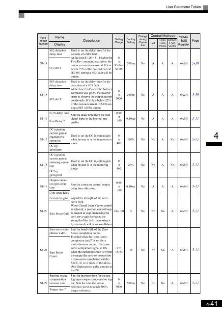
User Parameter Tables<br />
Parameter<br />
Number<br />
S1-14<br />
S1-15<br />
S1-16<br />
Name<br />
Display<br />
SE2 detection<br />
delay time<br />
SE2 det T<br />
SE3 detection<br />
delay time<br />
SE3 det T<br />
Description<br />
Used to set the delay time for the<br />
detectio of a SE2 fault.<br />
At the time S1-06 + S1-14 after the<br />
Fwd/Rev command was given the<br />
output current is measured. If it is<br />
below 25% of the no-load current<br />
(E2-03) setting a SE2 fault will be<br />
output.<br />
Used to set the delay time for the<br />
detection of a SE3 fault.<br />
At the time S1-15 after the fwd/rev<br />
command was given, the inverterstarts<br />
to observe the output current<br />
continously. If it falls below 25%<br />
of the no-load current (E2-03) setting<br />
a SE3 will be output.<br />
RUN delay time Sets the delay time from the Run<br />
signal input to the internal run<br />
Run Delay T enable.<br />
Setting<br />
Range<br />
0<br />
to<br />
S1-04 -<br />
S1-06<br />
0<br />
to<br />
5000<br />
0.00<br />
to<br />
1.00<br />
Factory<br />
Setting<br />
Control Methods<br />
V/f<br />
Open<br />
Loop<br />
Vector<br />
Closed<br />
Loop<br />
Vector<br />
Change<br />
during<br />
Operation<br />
MEMO-<br />
BUS<br />
Register<br />
Page<br />
200ms No A A A 6A1H 5-39<br />
200ms No A A A 6A2H 5-39<br />
0.10sec No A A A 6A3H 5-11<br />
S1-17<br />
S1-18<br />
S1-19<br />
S1-20<br />
S1-21<br />
S1-22<br />
DC injection<br />
current gain at<br />
regenerative<br />
operation<br />
DC Inj<br />
gain@gen<br />
DC injection<br />
current gain at<br />
motoring operation<br />
DC Inj<br />
gain@mot<br />
Output contactor<br />
open delay<br />
time<br />
Cont open delay<br />
Zero-servo gain<br />
Zero Servo Gain<br />
Zero-servo completion<br />
width<br />
Zero Servo<br />
Count<br />
Starting torque<br />
compensation<br />
increase time<br />
Torque incr T<br />
Used to set the DC injection gain<br />
when inveter is in the regerenative<br />
mode.<br />
Used to set the DC injection gain<br />
when inveter is in the motoring<br />
mode.<br />
Sets the contactor control output<br />
delay time after stop.<br />
0<br />
to<br />
400<br />
0<br />
to<br />
400<br />
0.00<br />
to<br />
1.00<br />
100% No No A No 6A4H 5-11<br />
20% No No A No 6A5H 5-11<br />
0.10sec No A A A 6A6H 5-11<br />
Adjust the strength of the zeroservo<br />
lock.<br />
When Closed Loop Vector control<br />
is selected, a position control loop<br />
is created at stop. Increasing the<br />
zero-servo gain increases the<br />
strength of the lock. Increasing it<br />
by too much will cause oscillation.<br />
0 to 100 5 No No No A 6A7H 5-11<br />
Sets the bandwidth of the Zero<br />
Servo completion output.<br />
Enabled when the “zero-servo<br />
completion (end)” is set for a<br />
multi-function output. The zeroservo<br />
completion signal is ON<br />
when the current position is within<br />
the range (the zero-servo position<br />
+ zero-servo completion width.)<br />
Set S1-21 to 4 times of the allowable<br />
displacement pulse amount at<br />
the PG.<br />
Sets the increase time for the analog<br />
input torque compensation signal.<br />
Sets the time the torque<br />
reference needs to reach 300%<br />
torque reference.<br />
0 to<br />
16383<br />
0<br />
to<br />
5000<br />
10 No No No A 6A8H 5-11<br />
500ms No No No A 6A9H 5-11<br />
4<br />
4-41


